Tunable semiconductor laser apparatus with external resonator
a semiconductor laser and external resonator technology, applied in semiconductor lasers, instruments, optical elements, etc., can solve the problems of inability to describe a specific rotary drive mechanism of the band pass filter, the total external resonator inevitably becomes large in size, and it is difficult to downsize and cost-cut the laser light source. , to achieve the effect of improving mass-productivity, shortening the length of the external resonator, and reducing the total apparatus
- Summary
- Abstract
- Description
- Claims
- Application Information
AI Technical Summary
Benefits of technology
Problems solved by technology
Method used
Image
Examples
embodiment 1
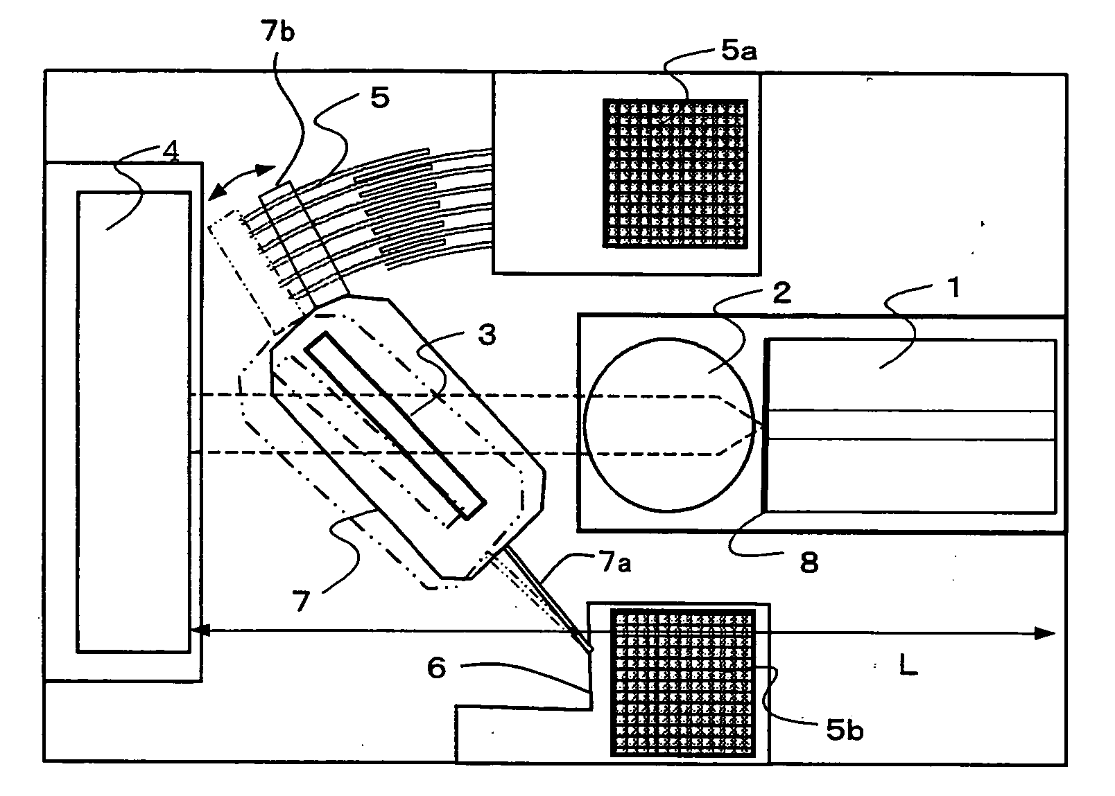
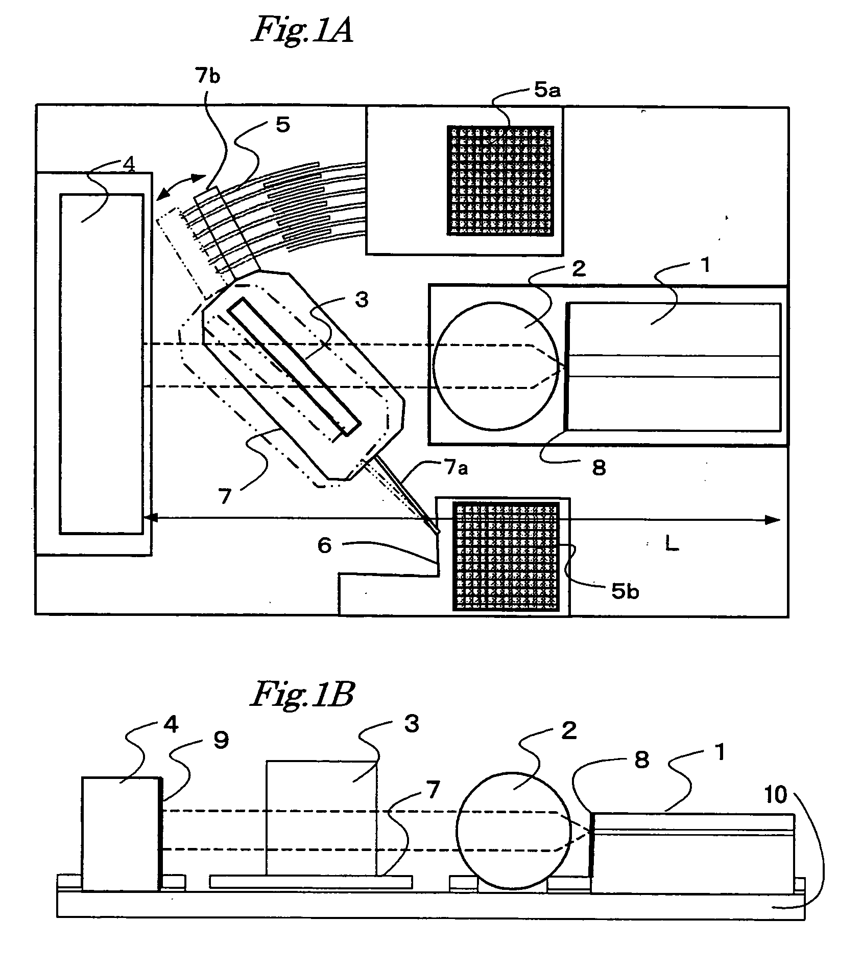
[0036]FIG. 1A is a plan view showing the first embodiment according to the present invention, and FIG. 1B is a side view thereof. A tunable semiconductor laser apparatus includes a semiconductor laser device 1, a light collecting device 2 for collecting light emitted from the semiconductor laser device 1, a reflecting device 4 for reflecting light from the light collecting device 2, a tunable device 3 having narrow band pass characteristics, and an angular displacement driving mechanism for angularly displacing the tunable device 3. These components are mounted on a base 10.
[0037] The semiconductor laser device 1 has two optical end faces, and one end face on the side of the reflecting device 4 is coated with a antireflection film 8. Another end face outside may have no coating or may be coated with a reflecting film having a predetermined reflectance. The oscillation wavelength of the semiconductor laser device 1 may be selected appropriately for applications of light source, for ...
embodiment 2
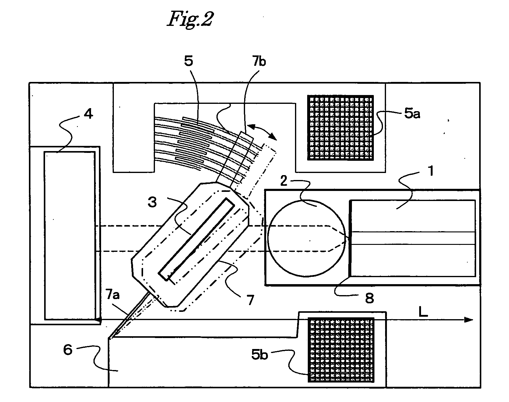
[0066]FIG. 10 is a plan view showing the second embodiment according to the present invention. A tunable semiconductor laser apparatus includes a semiconductor laser device 1, a light collecting device 2 for collecting light emitted from the semiconductor laser device 1, a reflecting device 4 for reflecting light from the light collecting device 2, a tunable device 3 having narrow band pass characteristics, and an angular displacement driving mechanism for angularly displacing the tunable device 3. These components are mounted on a base 10.
[0067] The semiconductor laser device 1, the light collecting device 2, the tunable device 3 and the reflecting device 4 are similar in configuration and operation to those of the first embodiment, hereinafter tautological description will be omitted.
[0068] In this embodiment, the micro-machine actuator 5 is mounted at a location different from that in FIG. 1 in the angular displacement driving mechanism for angularly displacing the tunable devi...
embodiment 3
[0075]FIGS. 11A and 11B are plan views showing the third embodiment according to the present invention. In this embodiment, the tunable device 3 and the angular displacement driving mechanism for angularly displacing the tunable device 3 constitutes a tunable unit 30.
[0076] The semiconductor laser device 1, the light collecting device 2, the tunable device 3 and the reflecting device 4 are similar in configuration and operation to those of the first embodiment, hereinafter tautological description will be omitted.
[0077] The tunable unit 30 includes the tunable device 3 having narrow band pass characteristics, the angular displacement driving mechanism for angularly displacing the tunable device 3 constitutes a tunable unit 30, and a unit base 31 for supporting these components. The tunable unit 30 is configured separately from the base 10 as shown in FIG. 1, subsequently mounted on the base 10 at an assembly step for the tunable semiconductor laser apparatus.
[0078] First, in FIG....
PUM
 Abstract
Description
Claims
Application Information
 - R&D
- Intellectual Property
- Life Sciences
- Materials
- Tech Scout
- Unparalleled Data Quality
- Higher Quality Content
- 60% Fewer Hallucinations
Browse by: Latest US Patents, China's latest patents, Technical Efficacy Thesaurus, Application Domain, Technology Topic, Popular Technical Reports.
© 2025 PatSnap. All rights reserved.Legal|Privacy policy|Modern Slavery Act Transparency Statement|Sitemap|About US| Contact US: help@patsnap.com


