Paper conveyance apparatus
a paper conveyancing and apparatus technology, applied in the direction of article delivery, thin material handling, article separation, etc., to achieve the effect of stable paper feeding quality, reduced paper conveyancing speed, and low variation in the stopping position of paper
- Summary
- Abstract
- Description
- Claims
- Application Information
AI Technical Summary
Benefits of technology
Problems solved by technology
Method used
Image
Examples
first specific example
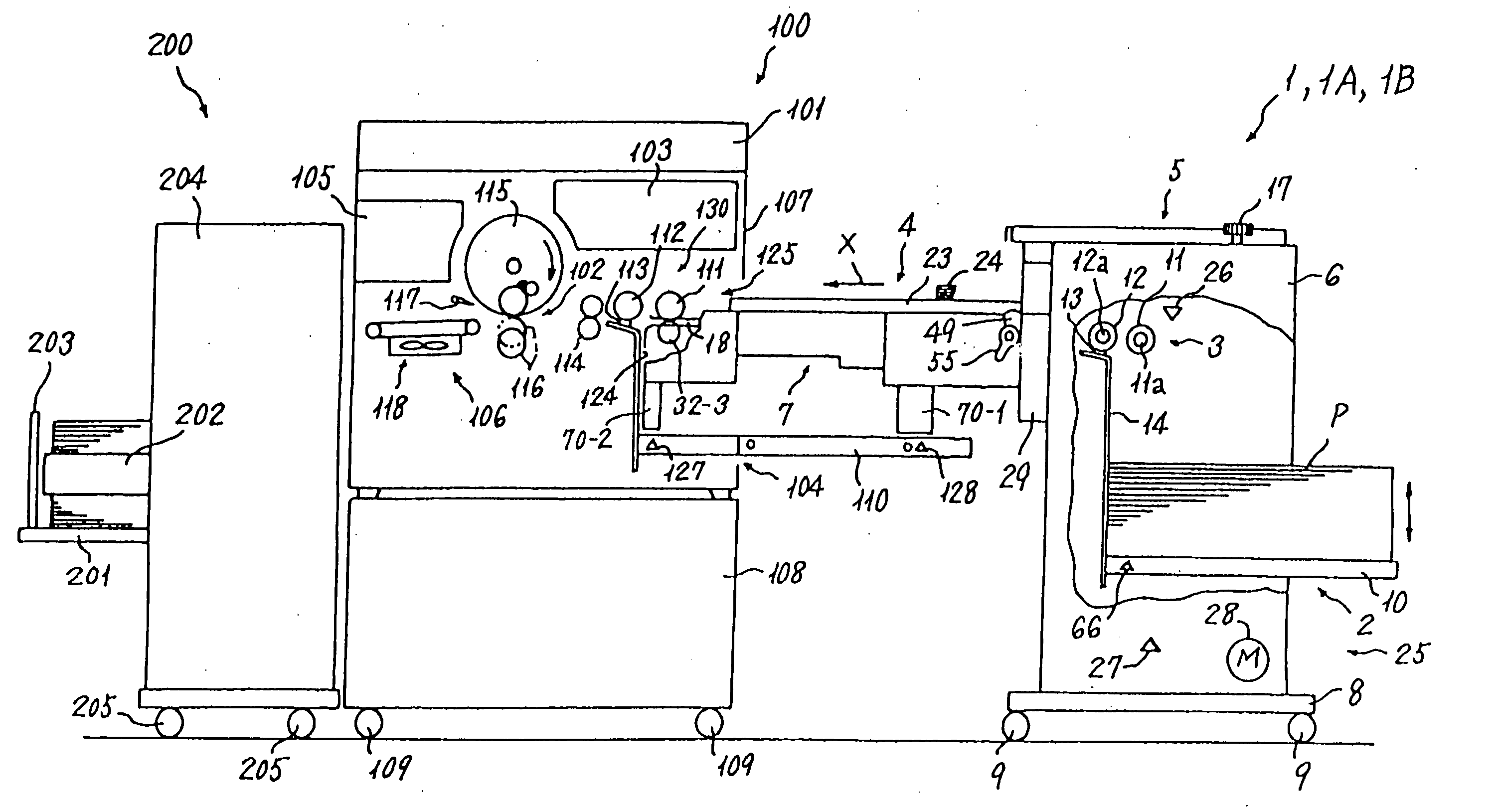
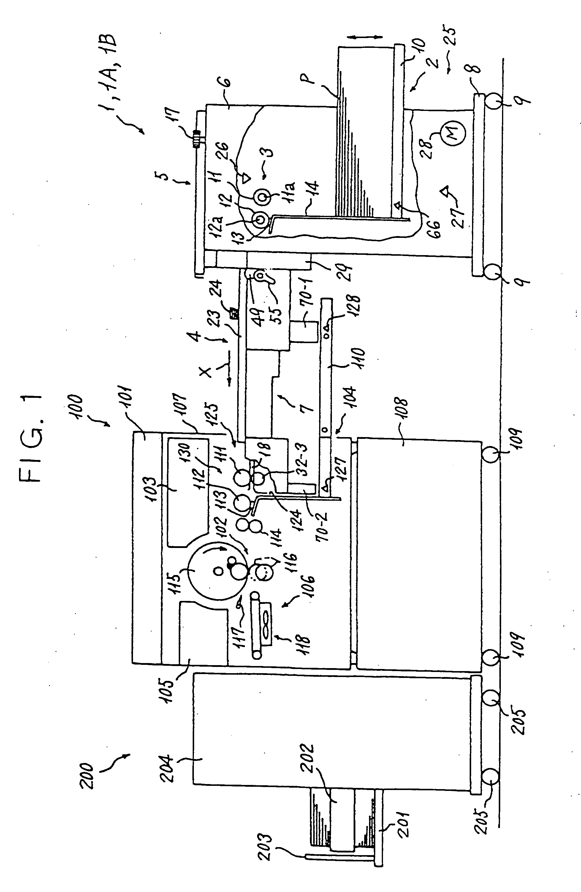
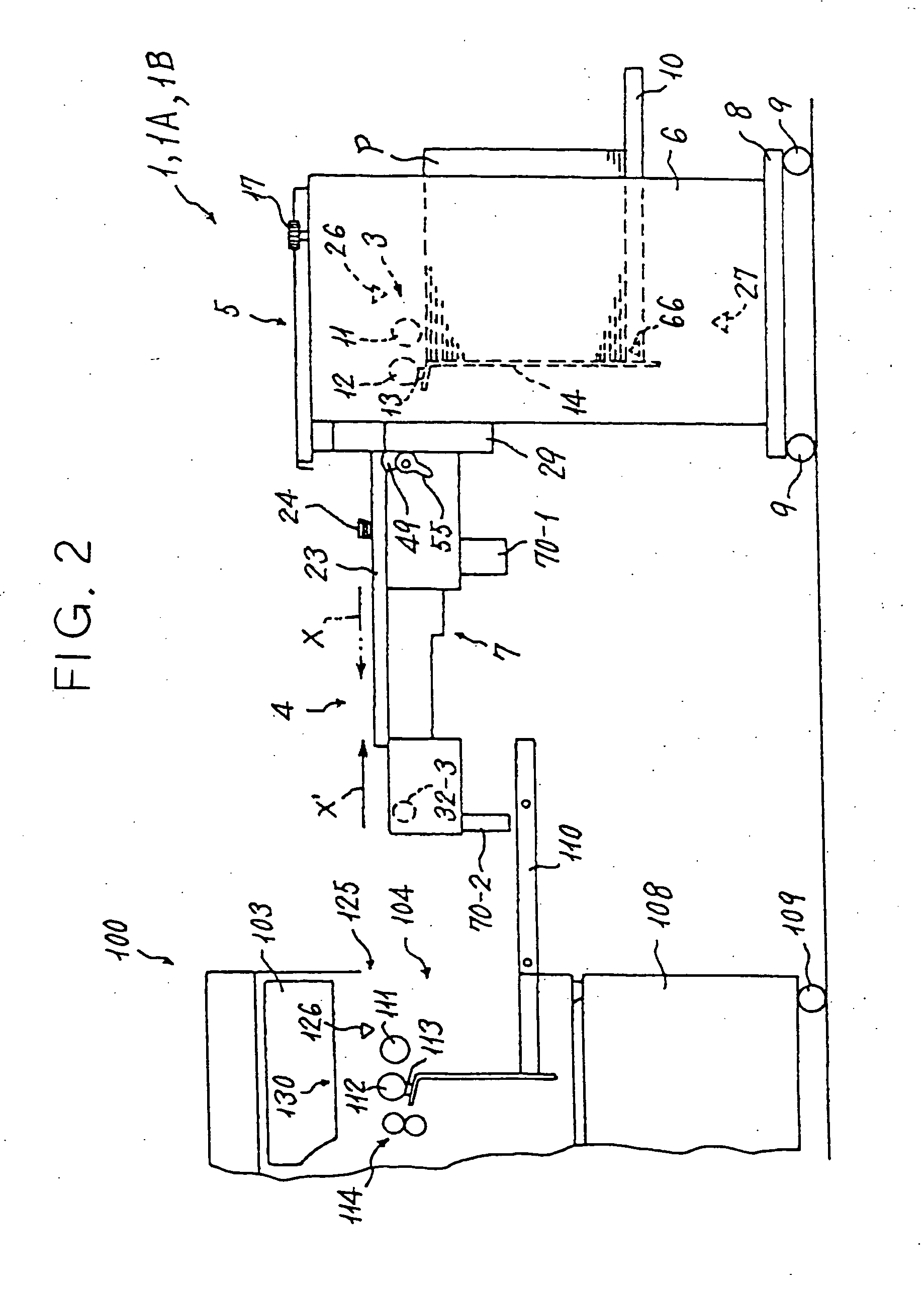
[0274] A bulk feed / conveyance unit 1A serving as a paper conveyance apparatus pertaining to a first specific example of the present invention is shown in FIGS. 1 to 4 and 33. The bulk feed / conveyance unit 1A differs mainly from the bulk feed / conveyance unit 1 of the unpublished embodiment shown in FIGS. 1 through 32A and 32B in that the control apparatus 85 (CPU 86) is allocated a third function for performing the paper conveyance control to be described below.
[0275] The control apparatus 85 (CPU 86) comprises a third function as a control device for reducing the paper conveyance speed of the second paper conveyance device 30-2 and third paper conveyance device 30-3, disposed to the front and rear of the seventh sensor 50-7, when the leading edge of the paper P is detected by the seventh sensor 50-7, which is disposed one sensor further toward the upstream side of the intermediate conveyance path 18 than the eighth sensor 50-8, which is the furthest-downstream paper detecting devic...
second specific example
[0283] A bulk feed / conveyance unit 1B serving as a paper conveyance apparatus pertaining to a second specific example of the present invention is shown in FIGS. 1 to 4 and FIGS. 33 to 37. The bulk feed / conveyance unit 1B differs mainly from the bulk feed / conveyance unit 1A shown in FIGS. 1 to 4 and 33 in that a pair of plate springs 132 constituted by elastic members and serving as a braking force applying device for applying a braking force to the conveyed paper P are annexed to the rear end portion of the auxiliary upper guide plate 36, disposed on the intermediate conveyance path 18 between the eighth sensor 50-8 and the seventh sensor 50-7, which is disposed one sensor further toward the upstream side of the intermediate conveyance path 18 than the eighth sensor 50-8, as shown in FIGS. 34 through 37 and as will be described below.
[0284] As shown in FIGS. 34 to 37, each plate spring 132 is adhered and fixed to the rear surface of an upward-facing inclined portion on the rear end...
PUM
 Abstract
Description
Claims
Application Information
 - R&D
- Intellectual Property
- Life Sciences
- Materials
- Tech Scout
- Unparalleled Data Quality
- Higher Quality Content
- 60% Fewer Hallucinations
Browse by: Latest US Patents, China's latest patents, Technical Efficacy Thesaurus, Application Domain, Technology Topic, Popular Technical Reports.
© 2025 PatSnap. All rights reserved.Legal|Privacy policy|Modern Slavery Act Transparency Statement|Sitemap|About US| Contact US: help@patsnap.com


