
Dialysis catheter tip

a catheter tip and dialysis technology, applied in the field of dialysis catheter tip, can solve the problems of increasing the cost of the procedure, increasing the time required, and increasing patient discomfort, and achieve the effect of reducing the outflow velocity

Inactive Publication Date: 2005-08-18
RADIUS INT PARTNERSHIP
View PDF97 Cites 46 Cited by
  • Summary
  • Abstract
  • Description
  • Claims
  • Application Information

AI Technical Summary

Benefits of technology

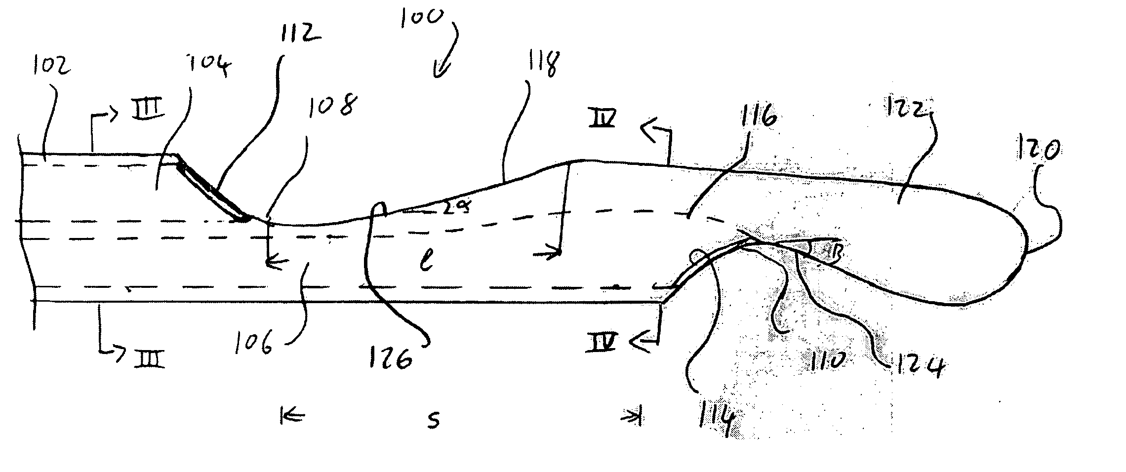
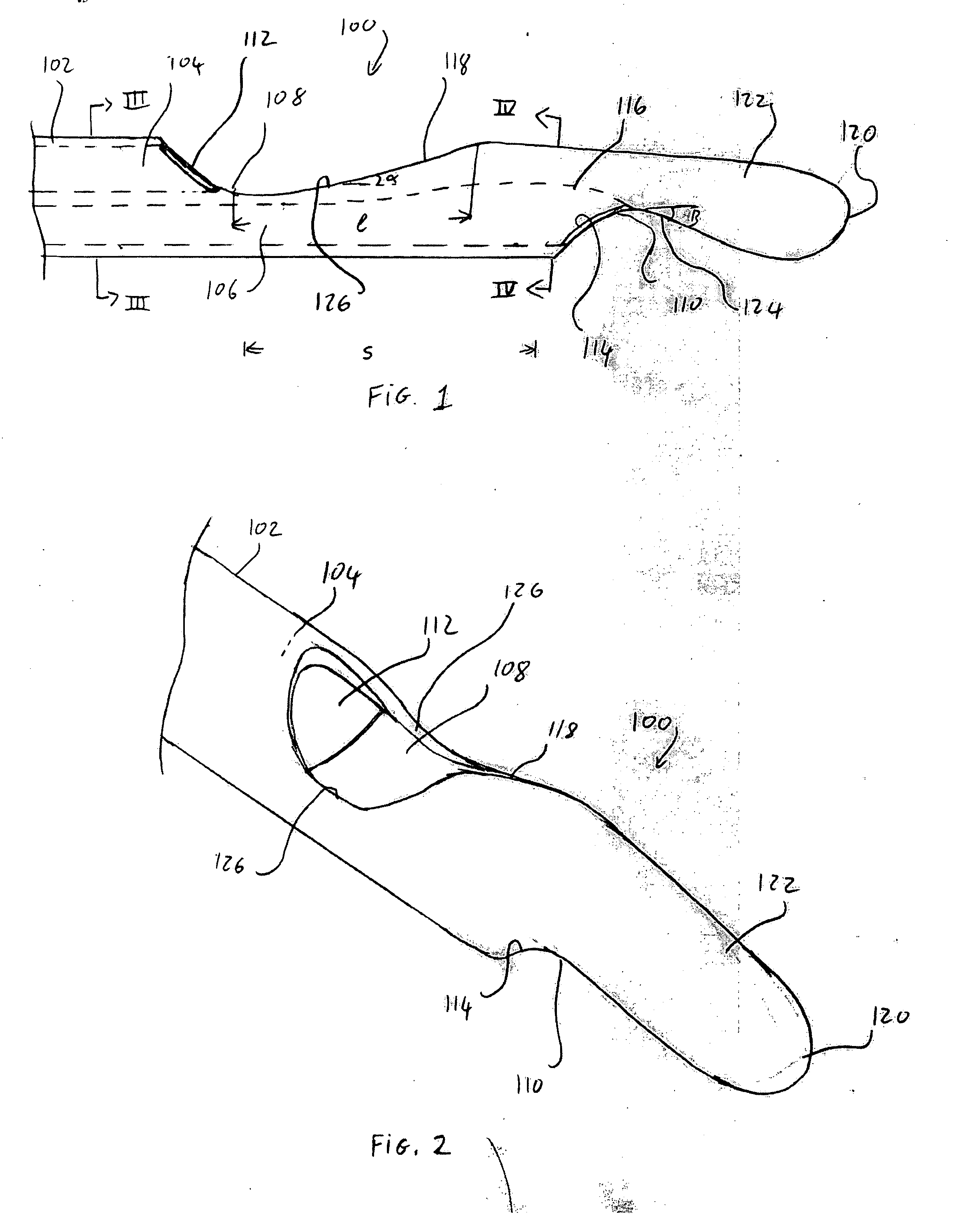
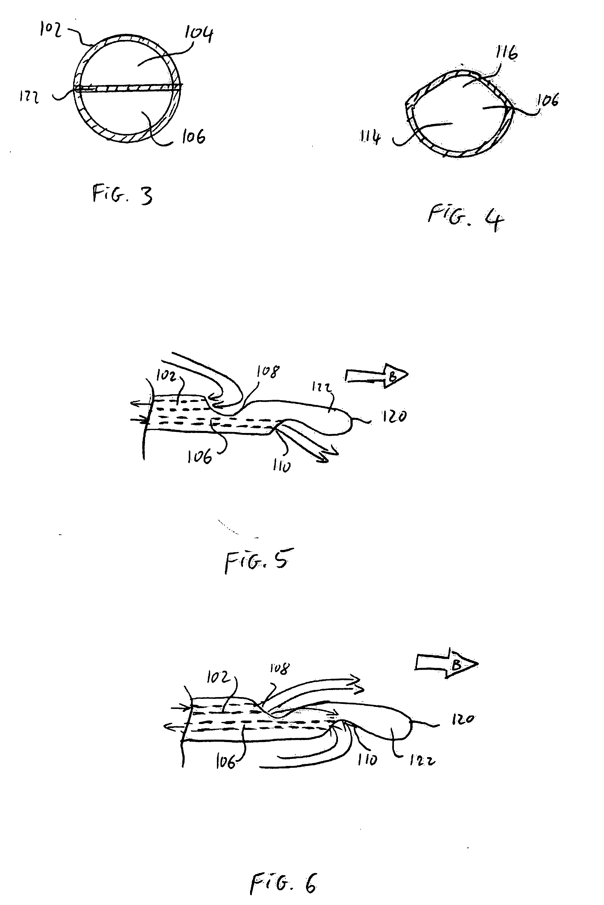
[0004] In one aspect, the present invention is directed to a distal tip for a catheter comprising first and second lumens extending therethrough, wherein in an operative configuration, the first and second lumens are coupled to first and second lumens of a dual lumen catheter and a first opening fluidly connected to the first lumen for inflow of fluid from a body lumen into which the distal tip is inserted in a normal mode of operation and for outflow of fluid thereto in a reverse mode of operation in combination with a second opening fluidly connected to the second lumen, the second opening being disposed distally from the first opening and separated therefrom by a selected stagger distance for outflow of fluid therefrom when the catheter is in the normal mode of operation and for inflow of fluid from the body lumen in a reverse mode of operation and a contoured flow deflection element directing, in the reverse mode of operation, outflow from the first opening away from the second opening. A contoured outlet portion of the second opening reduces an outflow velocity therefrom in the normal mode of operation.

Problems solved by technology

This delays treatment of portions of the venous blood which is displaced by the recirculating fluid thereby increasing the time required to achieve a desired amount of purification and, consequently, increasing the cost of the procedure and patient discomfort.

Method used


Image

  • Dialysis catheter tip
  • Dialysis catheter tip
  • Dialysis catheter tip

Examples


Embodiment Construction

[0018] The present invention may be further understood with reference to the following description and the appended drawings, wherein like elements are referred to with the same reference numerals. The present invention is related to medical devices that are used to access the vascular system of a patient. Although the present invention is described in regard to a catheter used to withdraw and return blood to the patient during dialysis, those skilled in the art will understand that the invention is equally applicable to any treatment in which a single catheter is used for the withdrawal of fluid from and the provision of fluid to a blood vessel or other body lumen. More particularly, the invention is related to catheter tips that minimize the amount of recirculation taking place during such treatments.

[0019] To reduce recirculation, the tips of conventional dialysis catheters are shaped, to a certain extent, to separate the inlet and outlet orifices. For example, conventional desi...


PUM


Abstract

A distal tip for a catheter comprises first and second lumens extending therethrough, wherein in an operative configuration, the first and second lumens are coupled to first and second lumens of a dual lumen catheter with a first opening of the distal tip fluidly connected to the first lumen for inflow of fluid from a body lumen into which the distal tip is inserted in a normal mode of operation and for outflow of fluid thereto in a reverse mode of operation and a second opening fluidly connected to the second lumen. The second opening is disposed distally from the first opening and separated therefrom by a selected stagger distance for outflow of fluid therefrom when the catheter is in the normal mode of operation and for inflow of fluid from the body lumen in a reverse mode of operation. The distal tip also includes a contoured flow deflection element directing, in the reverse mode of operation, outflow from the first opening away from the second opening and a contoured outlet portion of the second opening reducing an outflow velocity therefrom in the normal mode of operation.

Description

BACKGROUND OF THE INVENTION [0001] Medical procedures for the treatment of chronic diseases often require repeated access to the vascular system for the injection of therapeutic compounds and the sampling of blood. Kidney dialysis, chemotherapy and other chronic treatments generally rely on catheters for both injection to and withdrawal of fluids from the vascular system. For example, during a kidney dialysis treatment, large amounts of blood are withdrawn from the patient and treated externally in a dialysis machine to remove impurities and add nutrients, medications and any other desired therapeutic elements. This treated blood is then returned to the patient. [0002] Typically, a single catheter having two or more lumens is used for the removal and return of the blood with a first of the lumens being used to aspire impure blood from a blood vessel (usually a vein) and a second of the lumens being used to return the treated blood to the blood vessel. A single needle including inlet...

Claims


Application Information

Patent Timeline
IPC IPC(8): A61M25/00
CPCA61M25/003A61M25/0068A61M25/0069A61M2025/0073A61M2025/0031A61M2025/0037A61M25/0074
Inventor DIMATTEO, KRISTIANBEAUPRE, TODDCULHANE, JAMESBELL, BENJAMINWELDON, JAMES
Owner RADIUS INT PARTNERSHIP
Learn More