Digital predistorter using power series model
- Summary
- Abstract
- Description
- Claims
- Application Information
AI Technical Summary
Benefits of technology
Problems solved by technology
Method used
Image
Examples
first embodiment
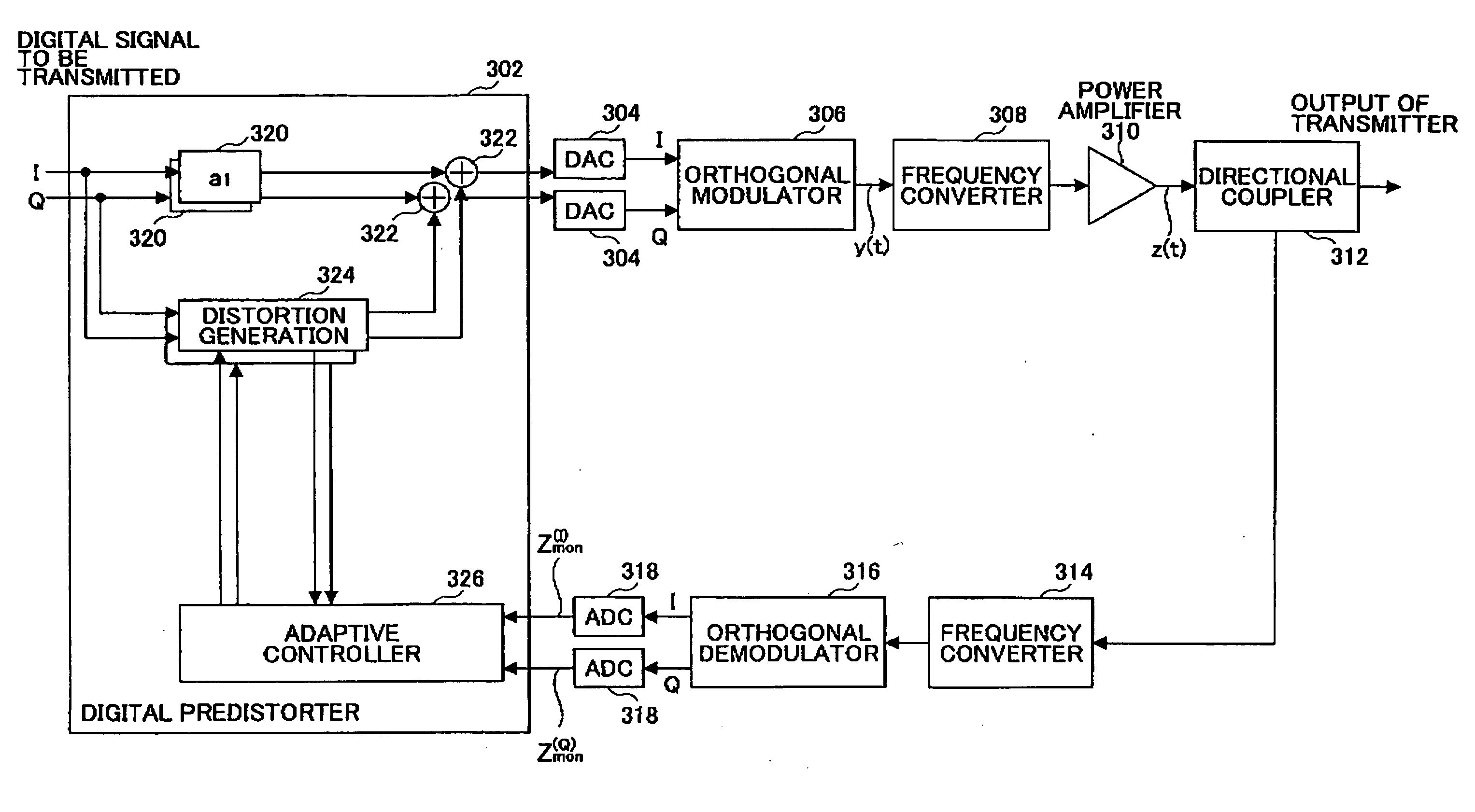
[0050]FIG. 3 is a schematic diagram illustrating a part of a transmitter using a digital predistorter according to the invention.
[0051] The signal transmission system of the transmitter includes a digital predistorter 302, a digital-to-analog converter (DAC) 304, an orthogonal modulator 306, a frequency converter 308, and a power amplifier 310. The feedback system of the transmitter includes a directional coupler 312, a frequency converter 314, an orthogonal demodulator 316, and an analog-to-digital converter (ADC) 318. The digital predistorter 302 has a pair of coefficient multipliers 320, a pair of adders 322, a pair of distortion generating units 324, and an adaptive controller 326.
[0052] The digital predistorter 302 receives a digital signal to be transmitted (referred to as a “digital transmission signal”), as indicated at the top left of the figure. The inphase component (I component) and the quadrature component (Q component) of the digital signal are input to the digital pr...
second embodiment
[0083]FIG. 12 is a block diagram of a digital predistorter 1202 according to the invention. The digital predistorter 1202 has a coefficient multiplier 1204 and an adder 1206 on the path for the fundamental wave, and has an adaptive controller 1226 on the feed-forward path. The digital predistorter 1202 also has a multiplier 1208, coefficient multiplier 1210, a finite impulse response filter FIR3 1212, and an adder 1214 on the path for the third order distortion. On the path for the fifth order distortion are provided a multiplier 1218, a coefficient multiplier 1220, a finite impulse response filter FIR5 1222, and an adder 1224. Although not shown in the figure, similar paths are provided for higher order distortion components.
[0084] Each of the coefficient multipliers 1204, 1210, and1220 multiplies the input signal by a prescribed constant (generally, a complex number) indicated as “a1”, “a3”, or “a5” in the figure. The third order multiplier 1208 raises the input signal to the thir...
third embodiment
[0094]FIG. 14 is a block diagram illustrating an example of the digital predistorter 1302 of the In this example, only the third order distortion is considered, and the fifth and higher order distortion components are neglected, as in the example shown in FIG. 5. The adaptive controller 1326 of this example includes a subtractor 1404 and an adaptive algorithm unit 1406. The power level of the feedback signal is regulated to the appropriate level in either the digital or analog domain. The power level may be adjusted in either domain. If the operating range of the analog-to-digital converter (ADC) 318 is not broad enough, then it is desired to adjust the power level of the signal in the digital domain. If the power level of the signal input to the ADC is adjusted to the lower level at the ADC with an insufficient operating range, the precision of the output signal from the ADC may be degraded. Since the gain of the power amplifier 310 is known, to what power level the feedback signa...
PUM
 Abstract
Description
Claims
Application Information
 - R&D
- Intellectual Property
- Life Sciences
- Materials
- Tech Scout
- Unparalleled Data Quality
- Higher Quality Content
- 60% Fewer Hallucinations
Browse by: Latest US Patents, China's latest patents, Technical Efficacy Thesaurus, Application Domain, Technology Topic, Popular Technical Reports.
© 2025 PatSnap. All rights reserved.Legal|Privacy policy|Modern Slavery Act Transparency Statement|Sitemap|About US| Contact US: help@patsnap.com


