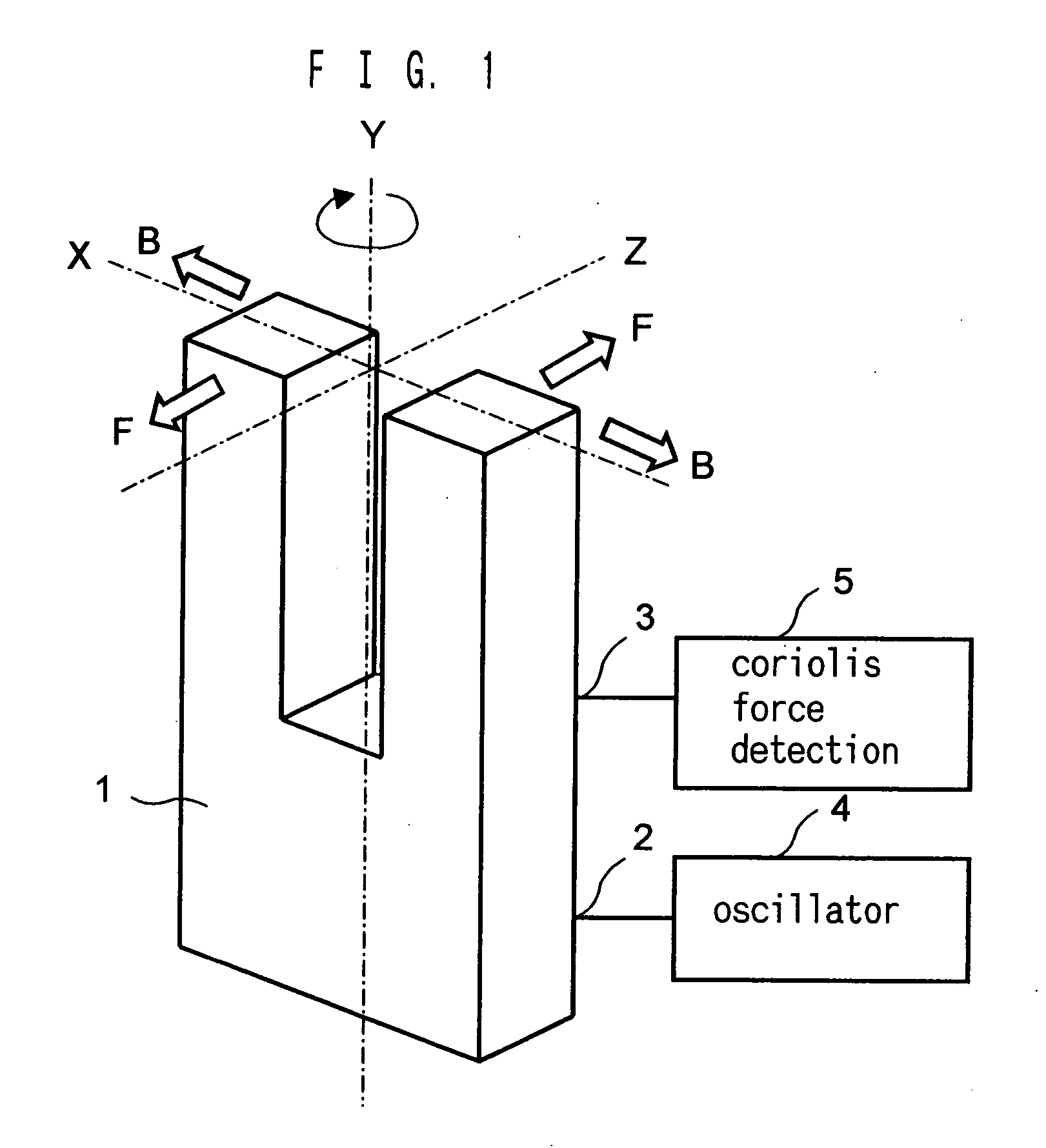
Angular velocity sensor
a technology angular velocity, which is applied in the direction of turn-sensitive devices, instruments, and device material selection, etc., can solve the problems of insufficient startup time reduction, danger of losing the function of angular velocity sensor, and insufficient output voltage of agc circuit, etc., to achieve high stability and precise angular velocity
- Summary
- Abstract
- Description
- Claims
- Application Information
AI Technical Summary
Benefits of technology
Problems solved by technology
Method used
Image
Examples
first embodiment (fig.2)
[0047] First Embodiment (FIG. 2)
[0048] The angular velocity sensor of FIG. 2, for example, is based on the same principle as the angular velocity sensor of FIG. 1, having the piezoelectric vibrator 11 such as crystal tuning fork vibrator. On the pre-determined positions of the piezoelectric vibrator 11, a first drive electrode 12a and a second drive electrode 12b for driving the piezoelectric vibrator 11, and a first detection electrode 13a and a second detection electrode 13b for detecting an electric charge depending on (for example, proportional to) an angular velocity ω applied to the piezoelectric vibrator 11, are prepared. An oscillator section 20 is connected to the drive electrodes 12a and 12b for supplying an AC drive voltage to the drive electrode 12b, which excites vibration of the piezoelectric vibrator 11 in a specific direction. An Coriolis output detection section 40 is connected to the detection electrode 13a and 13b, for outputting a DC detecting signal S out propor...
second embodiment (fig.3)
[0080] Second Embodiment (FIG. 3)
[0081] The temperature compensation type amplifier circuit of FIG. 3 is a circuit corresponding to the temperature compensation type amplifier circuit 22 inside the oscillator section 20 and the temperature compensation type amplifier circuit 45 inside the Coriolis output detection section 40 of FIG. 2.
[0082] The temperature compensation type amplifier circuit has an input terminal 101 connected to the output sides of the I / V converter circuit 21 or the high pass filter 44 of FIG. 2. An non-inverting input terminal of an Op amp 102 is connected to the input terminal 101. An output side of the Op amp 102 which is an output terminal 103 is connected to an input side of the gain switching circuit 24 or the synchronous detection circuit 46 of FIG. 2. In between an inverting input terminal of the Op amp 102 and the output side of output terminal 103, one of a feed back resistance 104 is connected. In between the inverting input terminal of the Op amp 102...
third embodiment (fig.4)
[0087] Third Embodiment (FIG.4)
[0088] A temperature compensation type amplifier circuit shown in FIG.4 corresponds to a circuit of the temperature compensation type amplifier circuit 22 inside the oscillator section 20 or the temperature compensation type amplifier circuit 45 inside the Coriolis output detection section 40 of FIG. 2.
[0089] This temperature compensation type amplifier circuit comprised of Nth inverting amplifier circuits with the identical circuit configuration using Op amps (provided that N is a positive integer no less than 2, for example N=2), and they are serially connected. The first inverting amplifier circuit has an input terminal 111 connected to an output side of the high pass filter 44 or the I / V converter circuit 21 of FIG. 2. On the input terminal 111, an inverting input terminal of the Op amp 113 is connected via one of the feedback resistance 112. In between the inverting input terminal and the output terminal of the Op amp 113, the other feedback resi...
PUM
 Abstract
Description
Claims
Application Information
 - R&D
- Intellectual Property
- Life Sciences
- Materials
- Tech Scout
- Unparalleled Data Quality
- Higher Quality Content
- 60% Fewer Hallucinations
Browse by: Latest US Patents, China's latest patents, Technical Efficacy Thesaurus, Application Domain, Technology Topic, Popular Technical Reports.
© 2025 PatSnap. All rights reserved.Legal|Privacy policy|Modern Slavery Act Transparency Statement|Sitemap|About US| Contact US: help@patsnap.com


