
Method and apparatus for two-port allpass compensation of polarization mode dispersion

a polarization mode and all-pass technology, applied in the field of optical fiber transmission systems, can solve the problems of limiting the channel capacity, differential group delay (dgd) between the two principle polarization modes, and polarization mode dispersion, and achieves the effects of reducing the value of the cost function, improving convergence, and reducing the cost function

Inactive Publication Date: 2005-08-11
LUCENT TECH INC
View PDF4 Cites 13 Cited by
  • Summary
  • Abstract
  • Description
  • Claims
  • Application Information

AI Technical Summary

Benefits of technology

[0005] Generally, a method and apparatus are disclosed for compensating for polarization mode dispersion using cascades of all-pass filters and directional couplers. The disclosed PMD compensator adjusts the coefficients of an adaptive filter structure involving all-pass filters and directional couplers based on a minimized cost function. In one implementation, a stochastic gradient algorithm, also referred to as the least mean square (LMS) algorithm, is employed to sequentially reduce the value of the cost function by the method of steepest descent. In another implementation, convergence is improved by employing a Newton algorithm that uses second derivatives to accelerate convergence.

Problems solved by technology

Polarization mode dispersion (PMD) is a fundamental problem in single-mode fiber optic communication systems that has limited the channel capacity.
Fiber asymmetry gives rise to random birefringence effects, resulting in differential group delay (DGD) between the two principle polarization modes.
Wavelength dependent coupling of the modes then leads to polarization mode dispersion, which becomes the dominant limiting factor of transmission rate as bandwidth increases.

Method used


Image

  • Method and apparatus for two-port allpass compensation of polarization mode dispersion
  • Method and apparatus for two-port allpass compensation of polarization mode dispersion
  • Method and apparatus for two-port allpass compensation of polarization mode dispersion

Examples


Embodiment Construction

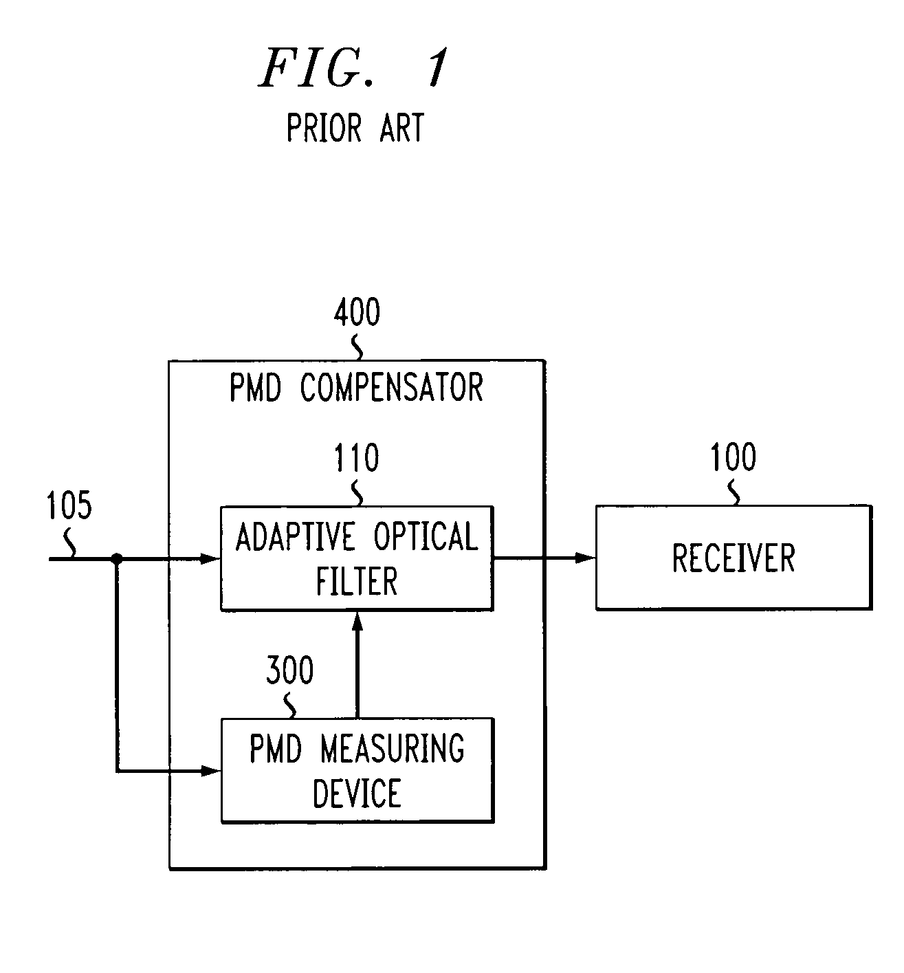
[0013] The present invention provides a method and apparatus for compensating for polarization mode dispersion using cascades of all-pass filters and directional couplers. The disclosed PMD compensator adjusts the coefficients of an adaptive filter structure involving all-pass filters and directional couplers based on a minimized cost function. Initially, the phase and amplitude of polarization components are evaluated in order to characterize the PMD of channels and adjust tunable PMD compensators. FIG. 1 is a schematic block diagram of a conventional optical receiver 100 that employs a PMD compensator 400, discussed below in conjunction with FIG. 4. Generally, the PMD compensator 400 employs a PMD measuring apparatus 300, discussed further below in conjunction with FIG. 3, to measure the PMD and an adaptive optical filter 110 to compensate for the measured PMD. The PMD compensator 400 may be integrated with or in the vicinity of the optical receiver 100.

[0014] As shown in FIG. 1,...


PUM


Abstract

A method and apparatus are disclosed for compensating for polarization mode dispersion using cascaded all-pass filters and directional couplers. The disclosed PMD compensator adjusts the coefficients of an adaptive filter structure involving all-pass filters and directional couplers based on a minimized cost function. In one implementation, a stochastic gradient algorithm, also referred to as the least mean square algorithm, is employed to sequentially reduce the value of the cost function by the method of steepest descent. In one another implementation, convergence is improved by employing a Newton algorithm that uses second derivatives to accelerate convergence.

Description

FIELD OF THE INVENTION [0001] The present invention relates generally to optical fiber transmission systems and, more particularly, to methods and apparatus for measuring and controlling polarization mode dispersion (PMD) in such optical fiber transmission systems. BACKGROUND OF THE INVENTION [0002] Optical communication systems increasingly employ wavelength division multiplexing (WDM) techniques to transmit multiple information signals on the same fiber at different optical frequencies. WDM techniques are being used to meet the increasing demands for improved speed and bandwidth in optical transmission applications, including fiber optic communication systems. [0003] Polarization mode dispersion (PMD) is a fundamental problem in single-mode fiber optic communication systems that has limited the channel capacity. Fiber asymmetry gives rise to random birefringence effects, resulting in differential group delay (DGD) between the two principle polarization modes. Wavelength dependent ...

Claims


Application Information

Patent Timeline
Patent Type & Authority Applications(United States)
IPC IPC(8): G02B6/26H04B10/12H04B10/18
CPCH04B10/2569
Inventor MORGAN, DENNIS R.
Owner LUCENT TECH INC
Learn More