
Screen, fresnel lens sheet used for the same, and image display apparatus using the same

Inactive Publication Date: 2005-08-11
HITACHI CONSUMER ELECTRONICS CORP +1
View PDF4 Cites 3 Cited by
  • Summary
  • Abstract
  • Description
  • Claims
  • Application Information

AI Technical Summary

Benefits of technology

[0007] The thinning-down (longitudinal downsizing) of the set can be achieved by reducing the projection distance by use of a wider-angle projection lens and further decentering the optical axis of the projection lens downward with respect to the center of the transmissive screen (e.g., aligning the optical-axis center of the projection lens with the central lower end of the transmissive screen).
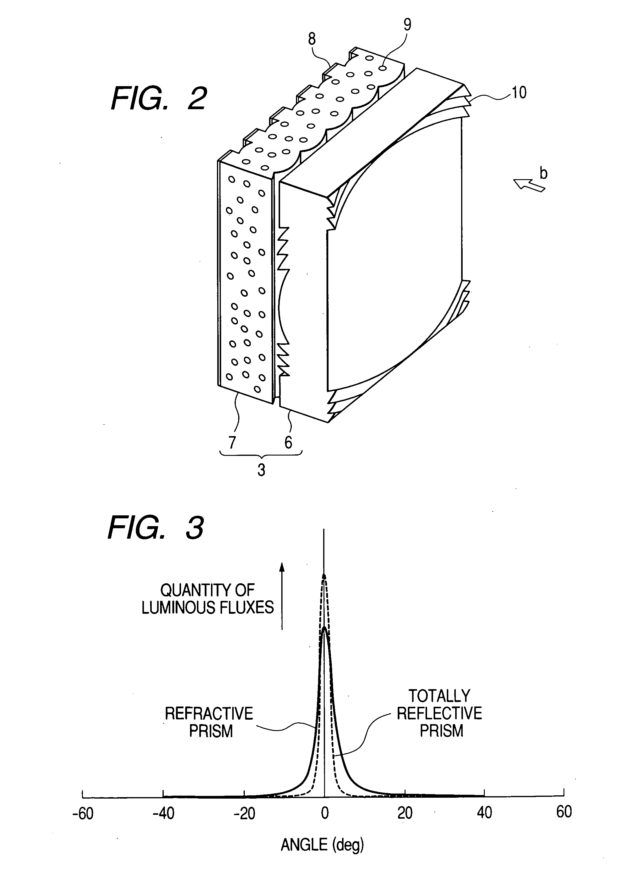
[0011] Accordingly, for a transmissive screen responding to the thinning-down of the set, it is important to reduce the reflection loss of light on the entrance plane of the screen and to improve utilization efficiency of the light and make the image brighter (i.e., to suppress decreases in the brightness of the image). It is also important to suppress the discontinuity of the light.
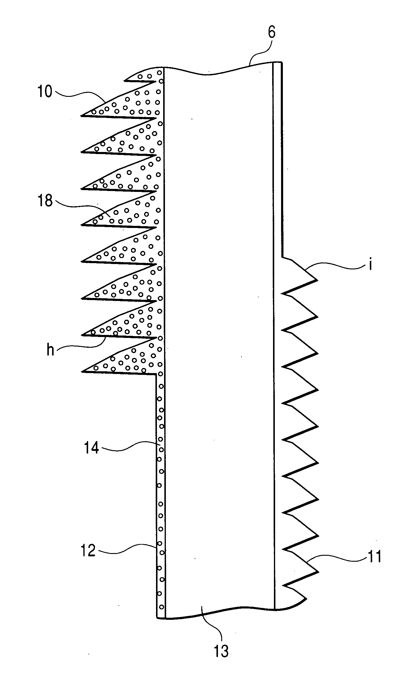
[0013] In the present invention, a totally reflective prism is formed in the region where light enters at an angle equal to or greater than a desired incident angle (e.g., approximately 40 degrees), at the image generation source side (on the entrance face of light) of a Fresnel lens sheet, and a refractive prism is formed at the image-watching side (on the exit face of the light). The foregoing totally reflective prism includes an entrance face at which the light comes in, and a totally reflective face on which the incoming light from the entrance face is reflected and from which the light exits toward the image-watching side. Also, the foregoing refractive prism is formed, at the image-watching side of the Fresnel lens sheet, in the range including a region present on a face opposite to that of a region in which the totally reflective prism is not formed. The refractive prism also includes a refractive face on which the foregoing light is refracted and from which the light exits toward the image-watching side. This refractive face is roughed to prevent multiple reflection from occurring between the refractive face and the plane of entrance that is disposed on a face opposite to that of the refractive face. The foregoing totally reflective face improves in reflection efficiency by being processed into a mirror surface state.
[0015] As described above, when a totally reflective prism and a refractive prism are to be formed at the image generation source side and image-watching side, respectively, of the Fresnel lens sheet, a prism configuration for making light go out in two directions or more may be adopted only for either the totally reflective prism or the refractive prism, or may be adopted for both thereof. If the above prism configuration is adopted for both, since the amount of occurrence of a flare and the direction of its occurrence can be made the same between both prisms, a change in brightness according to a particular watching angle can be suppressed very significantly.
[0017] Furthermore, a diffusing material may be contained in the ultraviolet-cured-type resin used to form the refractive prism, and / or in the ultraviolet-cured-type resin used to form the totally reflective prism. Hence, according to the present invention, it becomes possible to thin down an image display apparatus while at the same time obtaining high image quality.

Problems solved by technology

In the configuration described in Patent Document 1, however, since the configuration has refractive prisms on the light entrance surface of the Fresnel lens sheet, efficiency decreases and particularly a medium-band image (on the screen, a donut-like range) important for obtaining high image quality becomes dark.
If the discontinuity of light actually occurs, the image when viewed from the front will include discontinuous portions and deteriorate in image quality.

Method used


Image

  • Screen, fresnel lens sheet used for the same, and image display apparatus using the same
  • Screen, fresnel lens sheet used for the same, and image display apparatus using the same
  • Screen, fresnel lens sheet used for the same, and image display apparatus using the same

Examples


Embodiment Construction

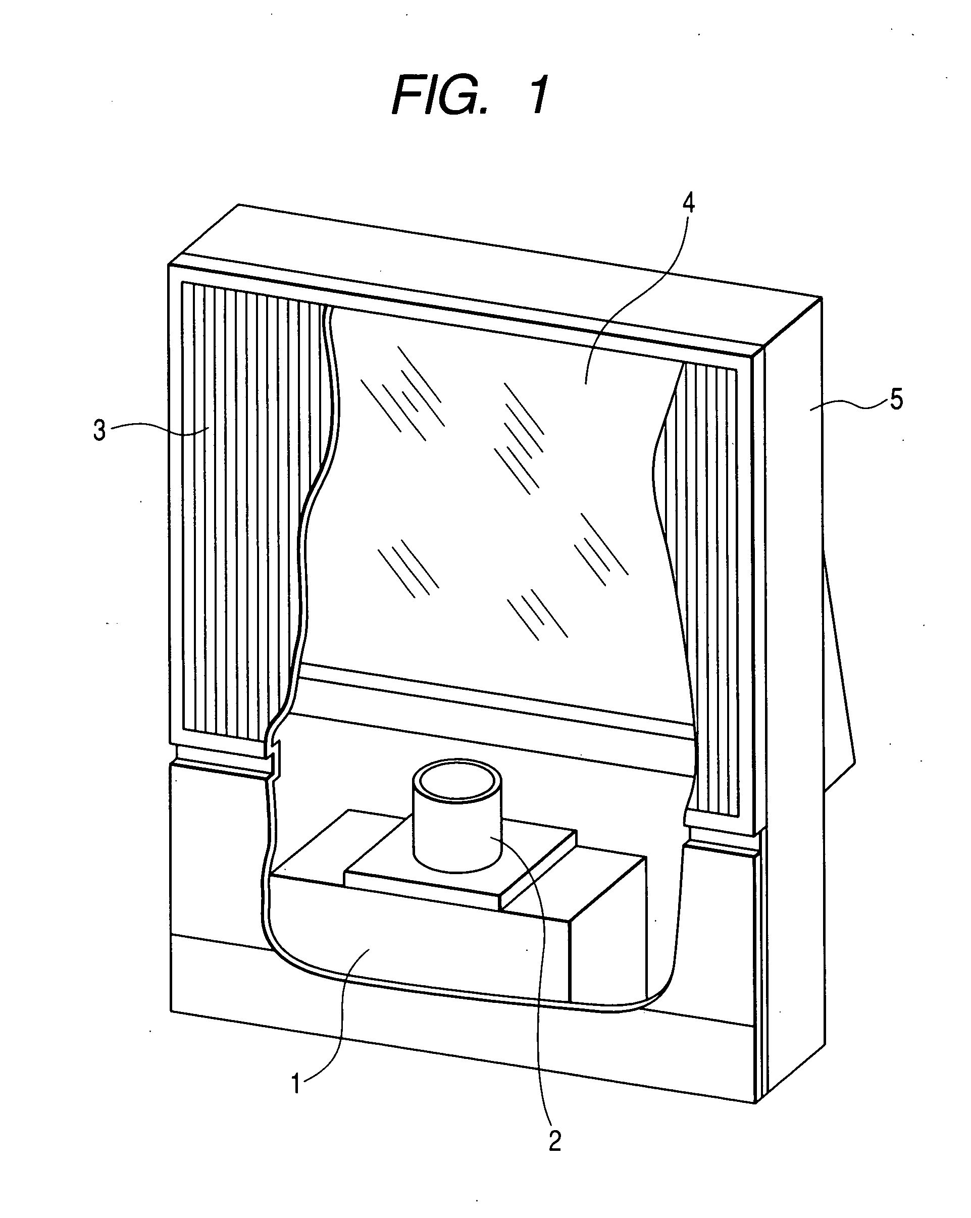
[0031] Embodiments of the present invention are described below referring to the accompanying drawings. FIG. 1 is a partially sectional, perspective view showing an example of an image display apparatus according to the present invention. An image generation source 1 includes a projection cathode-ray tube or a reflective or transmissive liquid-crystal panel, an image modulation element such as a display element having a plurality of very small mirrors, and other elements, and displays a compact image. Although a projection lens 2 projects the image onto a transmissive screen 3, since the projection lens is generally long in projection distance, a reflecting mirror 4 is provided halfway on an optical path of the projection lens in order to reduce a depth (longitudinal dimension) of the image display apparatus. These elements are fixed to a desired position inside a frame 5.

[0032]FIG. 2 is a schematic view showing a structure of a transmissive screen 3 according to the present invent...


PUM


Abstract

The present invention provides a technology that makes it possible to display high-quality images by reducing a reflection loss of the image light entering the upper left and right ends of a transmissive screen. At the image generation source side of the Fresnel lens sheet, a totally reflective prism section (10) is provided that totally reflects incident rays of light and causes the light to exit toward the image-watching side. At the image-watching side of the Fresnel lens sheet (6), a refractive prism section (11) is also provided that refracts the light entering from the totally reflective prism section (10) and causes the light to exit toward the image-watching side. The refractive prism section (11) has a roughed refractive face.

Description

CLAIM OF PRIORITY [0001] The present application claims priority from Japanese applications serial no. JP2004-031502, filed on Feb. 9, 2004 and serial no. JP2004-187229, filed on Jun. 25, 2004, the contents of which are hereby incorporated by reference into this application. BACKGROUND OF THE INVENTION [0002] (1) Field of the Invention [0003] The present invention relates to an image display apparatus for enlarging the images generated by an image generation source, and displaying the images in a projection format on a transmissive screen. The invention also relates to the screen and Fresnel lens sheet used for the image display apparatus. [0004] (2) Description of the Related Art [0005] A projection type of image display apparatus (hereinafter, this type of apparatus may be called the set) enlarges the images displayed by the projection cathode-ray tube or liquid-crystal display apparatus (or the like) that functions as a compact image generation source, projects the enlarged image...

Claims


Application Information

Patent Timeline
IPC IPC(8): G02B3/08G02B5/04G03B21/62G03B21/625
CPCG03B21/625
Inventor YOSHIKAWA, HIROKIOHISHI, TETSUHIRATA, KOJIIMAFUKU, DAISUKE
Owner HITACHI CONSUMER ELECTRONICS CORP
Learn More