
Switchable slot antenna

a slot antenna and switchable technology, applied in the structure of resonant antennas, polarised antenna unit combinations, radiating elements, etc., can solve the problem of very limited tuning range of the resulting antenna, and achieve excellent impedance matching and effective change of electrical length over a very wide bandwidth

Inactive Publication Date: 2005-08-11
RGT UNIV OF MICHIGAN
View PDF2 Cites 31 Cited by
  • Summary
  • Abstract
  • Description
  • Claims
  • Application Information

AI Technical Summary

Benefits of technology

[0007] The slot antenna proposed in the present invention uses shunt switches that effectively change its electrical length over a very wide bandwidth. To demonstrate the technique a reconfigurable slot antenna capable of operating at four different resonant frequencies over a bandwidth of 1.7:1 is designed and tested. Measurements of the return loss indicate that excellent impedance match can be obtained for all selected resonant frequencies. No special matching network is used and the matching properties are solely determined by the placement of the switches. The loading effect of the PIN diodes in the antenna is also characterized by a full wave analysis and transmission line theory and comparisons between the real and ideal switches are also studied. Per design goals, it is demonstrated that the reconfigurable slot antenna has the same radiation pattern at all frequencies. Also, the measured radiation patterns agree with the theoretical ones. The polarization characteristics and the efficiency behavior of the antenna as a function of frequency are investigated using both theoretical and experimental data Finally, some design guidelines are provided and possible design improvements are discussed.

Problems solved by technology

Although the radiation pattern properties could be preserved in all resonant frequencies, the tuning range of the resulting antenna was very limited.

Method used


Image

  • Switchable slot antenna
  • Switchable slot antenna
  • Switchable slot antenna

Examples


Embodiment Construction

[0036] The antenna size at UHF and lower becomes critical and therefore special consideration is required. A compact planar geometry is best suited since three-dimensional large and bulky structures are in general undesirable. Furthermore, some miniaturization techniques have been applied to reduce the size. This section focuses on the passive slot antenna design issues emanating from the above principles.

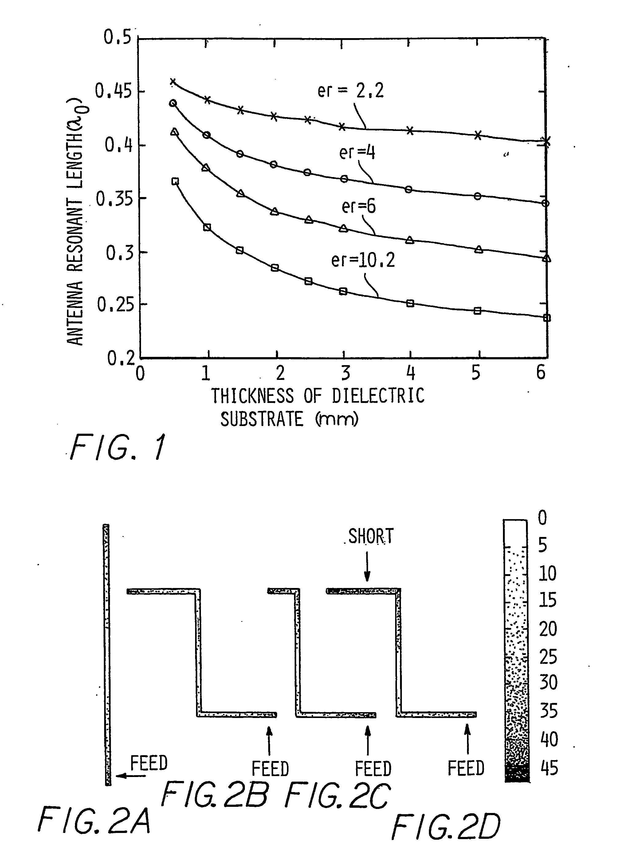
[0037] First, the miniaturization capabilities provided by a high dielectric constant substrate were investigated. Inasmuch as an accurate characterization of its effect is needed, a commercially available moment method code was employed. First, simple slot antennas were simulated at 600 MHz and their resonant lengths were determined as a function of the substrate thickness and dielectric constant (FIG. 1). This analysis suggests that even at low frequencies where the substrate is very thin compared to the wavelength, a miniaturization factor of about 2:1 is possible, if a high di...


PUM


Abstract

A compact, efficient and electronically tunable antenna is presented. A single-fed resonant slot loaded with a series of PIN diode switches constitute the fundamental structure of the antenna. The antenna tuning is real by changing its effective electrical length, which is controlled by the bias voltages of the solid state shunt switches along the slot antenna. Although the design is based on a resonant configuration, an effective bandwidth of 1.7:1 is obtained through this tuning without requiring a reconfigurable matching network. Four resonant frequencies from 540 to 890 MHz are selected in this bandwidth and very good matching is achieved for all resonant frequencies. Theoretical and experimental behavior of the antenna parameters is presented and it is demonstrated that the radiation pattern, efficiency and polarization state of the antenna remain essentially unaffected by the frequency tuning.

Description

FIELD OF THE INVENTION [0001] The present invention relates to a reconfigurable slot antenna having a plurality of shunt switches for changing an electrical length of the slot. BACKGROUND OF THE INVENTION [0002] With ever-increasing demand for reliable wireless communications, the need for efficient use of electromagnetic spectrum is on the rise. In modern wireless systems spread spectrum signals are used to suppress the harmful effects of the interference from other users who share the same channel (bandwidth) in a multiple-access communication system and the self-interference due to multipath propagation. Also spread spectrum signals are used for securing the message in the presence of unintended listeners and alleviating the effects of communication jammers. One common feature of spread spectrum signals is the relatively high bandwidth. This is specifically true for frequency-hopped spread spectrum communications system. In a frequency-hopped spread spectrum system a relatively l...

Claims


Application Information

Patent Timeline
Patent Type & Authority Applications(United States)
IPC IPC(8): H01Q1/38H01Q5/00H01Q13/10H01Q13/16H01Q21/24
CPCH01Q1/38H01Q9/14H01Q21/245H01Q13/106H01Q13/16H01Q13/103
Inventor PEROULIS, DIMITRIOSSARABANDI, KAMALKATEHI, LINDA P.
Owner RGT UNIV OF MICHIGAN
Learn More