Powder container, powder contained product, powder container manufacturing method, powder contained product reusing method, toner container and toner contained product

a technology of toner container and powder container, which is applied in the direction of electrographic process apparatus, packaging, instruments, etc., can solve the problems of difficult reuse of such containers, inability to obtain bonding strength for reuse of products, and process that took a long time to prepare for reuse, so as to achieve easy operation and reduce costs

Inactive Publication Date: 2005-08-04
KONICA MINOLTA BUSINESS TECH INC
View PDF5 Cites 19 Cited by
  • Summary
  • Abstract
  • Description
  • Claims
  • Application Information

AI Technical Summary

Benefits of technology

[0047] According to the invention given in (1), a cylinder thickness t is 0.3 mm≦t≦5.0 mm and a cylinder thickness deviation is Δt≦20%. This arrangement ensures that the convex spiral flute on the inner periphery of this cylindrical form and concave spiral flute on the outer periphery are not crushed, and drastically improves the transportability of toner inside the toner container, thereby ensuring a smooth supply of toner into the development apparatus even when there is only a small amount of toner in the toner container.
[0126] Similarly to the container body and engagement member, the locking member in the present invention is suited for reuse, because it is highly resistant to contamination by powder. Should it be contaminated, contamination can be easily removed.

Problems solved by technology

Hei 10-104922, the slide cover is provided with embossing treatment, and reuse of such a container has been found out to be difficult.
In other words, the embossed surface where the sealing material has been deposited is roughened, and the bonding strength permitting the reuse of a product cannot be obtained even if the sealing material is deposited.
However, processing of the embossed surface was to add a process that took much time in preparing for reuse.
Further, setting the deposition temperature to a higher level increased the energy consumption and raised the environmental load and processing costs.
These measures have failed to achieve the object of cutting down the cost and environmental load by reuse of the container.
Further, if the sealing material is bonded at a higher deposition temperature, variations occur in the deposition strength for each container, and it has become difficult to ensure handling quality including smooth separation.
This arrangement results in difficulties in removing engagement portions.
At present, however, it is difficult to find out a container where disengagement of parts is easy, under the pretext of meeting the requirements for process reduction achieved by creating a rigid fitting at the time of manufacture and the requirements for cost reduction.
Further, undue force must be applied to these containers at the time of disengagement of parts, so deterioration will develop due to the load locally applied to the member at the time of disengagement, and constituent members are damaged.
Such problems have occurred so far.
Reuse of the container is hindered by the damage of the constituent members resulting from the load applied to the members at the time of disengagement.
However, when a tool is used to grip the container body, the container body may be damaged, or deteriorated due to fatigue.
It has been not possible to manufacture such a container economically without such investment, according to the prior art.

Method used


Image

  • Powder container, powder contained product, powder container manufacturing method, powder contained product reusing method, toner container and toner contained product
  • Powder container, powder contained product, powder container manufacturing method, powder contained product reusing method, toner container and toner contained product
  • Powder container, powder contained product, powder container manufacturing method, powder contained product reusing method, toner container and toner contained product

Examples


Embodiment Construction

[0145] [Description of the Preferred Embodiment—1]

[0146] Referring to drawings, the following describes the embodiments of a toner container and toner supply apparatus according to the present invention, without the present invention being restricted thereto.

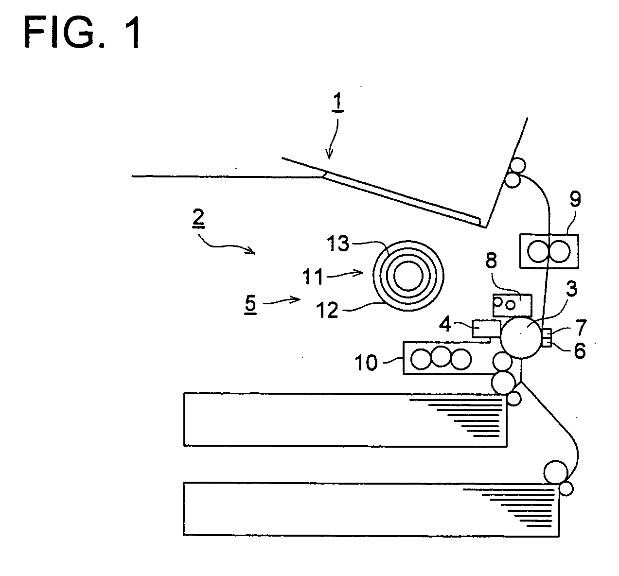
[0147]FIG. 1 is a front view of the vertical cross section schematically representing the overall structure of a plain paper copying machine 1 as an image forming apparatus. A drum-shaped photoconductor 3 is installed approximately at the center of the case 2 of the plain paper copying machine 1. An electrostatic charging and exposure apparatus 4, a development apparatus 5, a transfer unit 6, a separator 7, a cleaning apparatus 8 and others are arranged around this photoconductor 3. The development apparatus 5 comprises a development unit 10 and a toner supply apparatus 11.

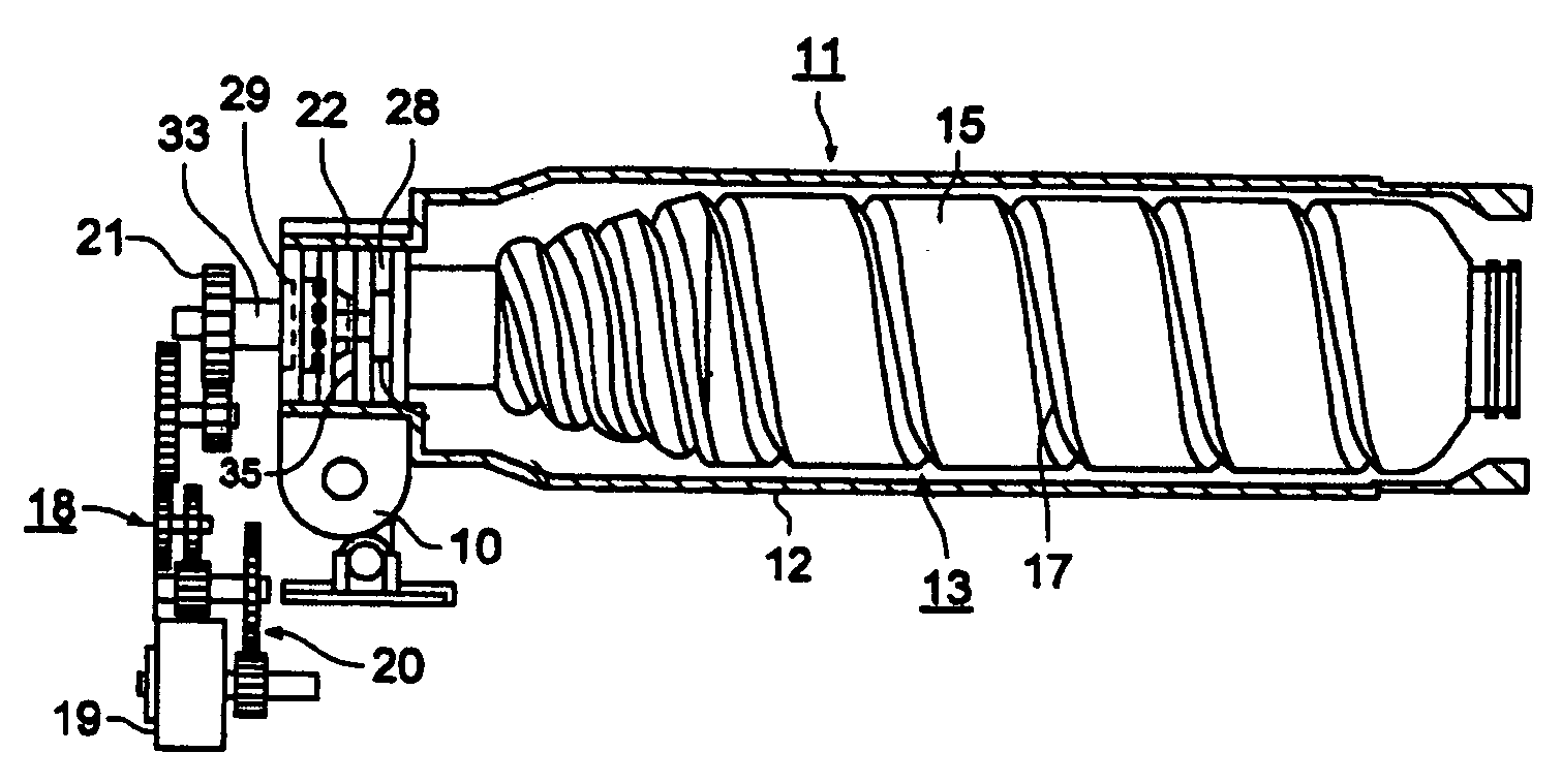
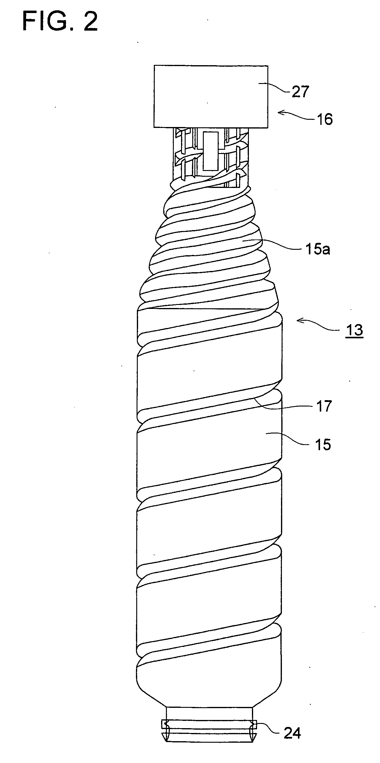
[0148] Further, in the toner supply apparatus 11 a cylindrical toner container holding member 12 is secured on the development unit 10. A cylindrical toner ...


PUM


Abstract

A toner container for supplying and / or replenishing toner into a development apparatus of image forming apparatus, by being engaged with the rotation transfer member of the development apparatus and being rotated about a center axis of the toner container integrally with the rotation transfer member. The toner container is structured with a cylindrical body having a toner outlet on one end of the cylindrical body, nearby a center axis of the cylindrical body, a convex spiral flute formed on the inner periphery of the cylindrical body, and a concave spiral flute formed on the outer periphery of the cylindrical body, wherein a ratio L / D of length L to diameter D of the cylindrical body is in a range of ½≦L / D≦10, a thickness of the cylindrical body t is 0.3 mm≦t≦5.0 mm; and a thickness deviation of the cylindrical body is Δt≦20%.

Description

BACKGROUND OF THE INVENTION [0001] The present invention relates to a toner container and toner supply apparatus used for an image forming apparatus such as a copying machine and printer. [0002] [Prior Art—1][0003] Such an image forming apparatus includes an apparatus wherein one end of the cylindrical toner container having a toner outlet on one end is engaged with a rotation transfer member of an development apparatus provided inside the image forming apparatus, and the toner container is rotated about the centerline of the toner container integrally linked with the rotation transfer member, whereby toner in the toner container is discharged from the toner outlet and is supplied to the development apparatus. [0004] [Problems to be Solved by the Invention—1][0005] A toner container and toner supply apparatus used in an image forming apparatus for electrophotography are required to meet the high speed of the image forming apparatus. In other words, it is necessary to increase the ca...

Claims


Application Information

Patent Timeline
IPC IPC(8): G03G15/08
CPCG03G2215/0668G03G2215/0685G03G2215/0687G03G15/0894G03G15/0872G03G15/0882Y10S222/01
Inventor YOSHINO, MASAHIRONAKANISHI, TATSUOTOYOIZUMI, YOSHIHIKO
Owner KONICA MINOLTA BUSINESS TECH INC
Why Eureka
Try Eureka