
Display apparatus, and driving circuit for the same

a technology for driving circuits and display devices, applied in static indicating devices, instruments, electroluminescent light sources, etc., can solve problems such as large power consumption in the interface between the control circuit b and the response speed

Active Publication Date: 2005-08-04
RENESAS ELECTRONICS CORP
View PDF5 Cites 285 Cited by
  • Summary
  • Abstract
  • Description
  • Claims
  • Application Information

AI Technical Summary

Benefits of technology

[0028] In the first gradation voltage generating circuit, a first reference voltage generating circuit generates a plurality of voltages, and a first selector circuit selects a first reference voltage and a second reference voltage from the plurality of voltages supplied from the reference voltage generating circuit based on the first setting data. A first voltage follower circuit carries out impedance conversion of the first reference voltage and the second reference voltage, and a first resistance string circuit voltage-divides a voltage difference between the first reference voltage and the second reference voltage after the impedance conversion and generates the plurality of first gradation voltages. Instead, in the first gradation voltage generating circuit, a first reference voltage generating circuit may generate a plurality of voltages, and a first selector circuit may select a first reference voltage and a second reference voltage from the plurality of voltages supplied from the reference voltage generating circuit based on the first setting data. A first voltage follower circuit carries out impedance conversion of the first reference voltage and the second reference voltage, and a second resistance string circuit voltage-divides a voltage difference between the first reference voltage and the second reference voltage after the impedance conversion and generates a plurality of voltages. A correcting circuit corrects the plurality of voltages generated by the second resistance string circuit based

Problems solved by technology

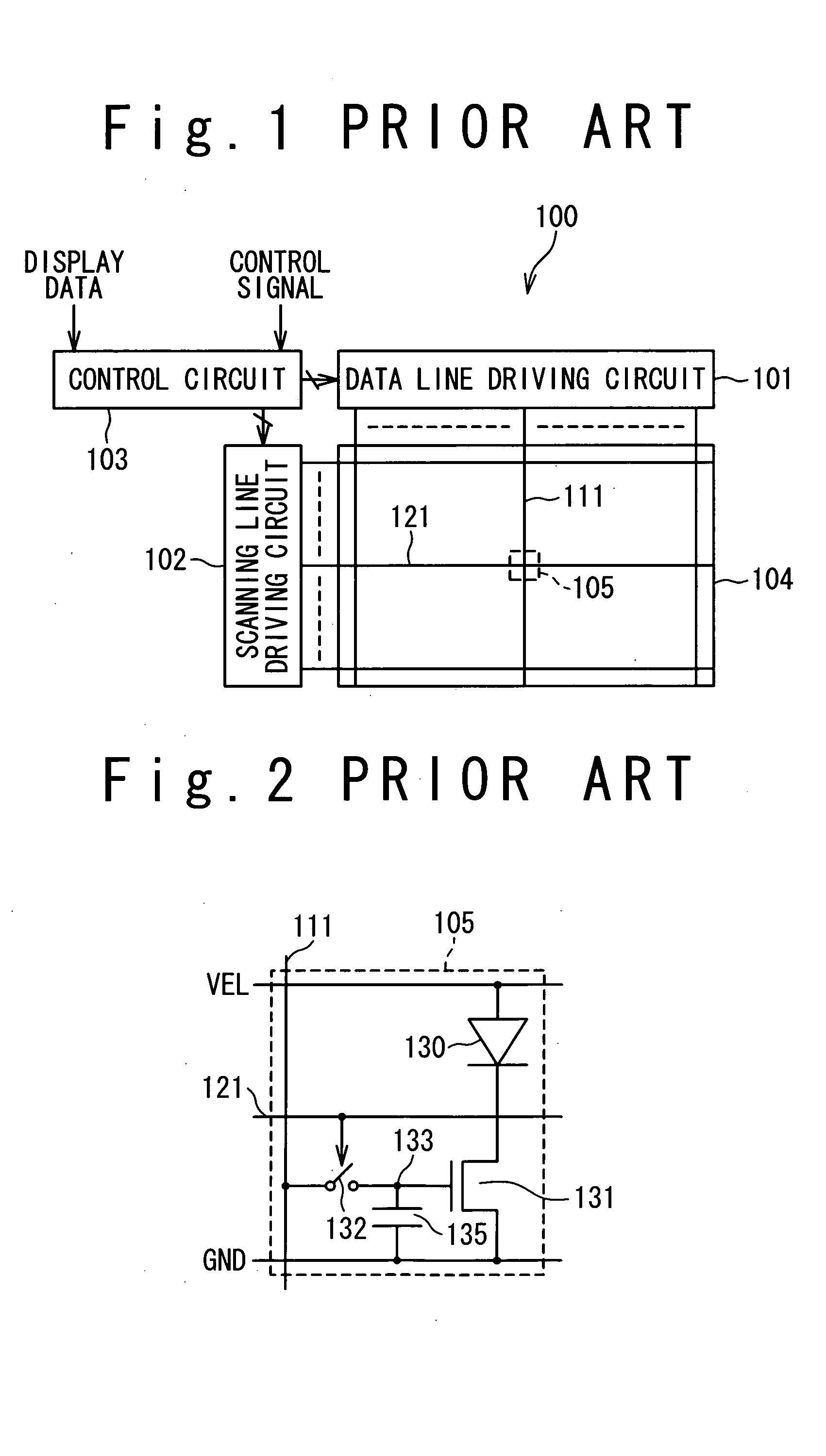
However, the method has a problem in a response speed.
Therefore, it is not suitable for a large-size display such as a television screen.
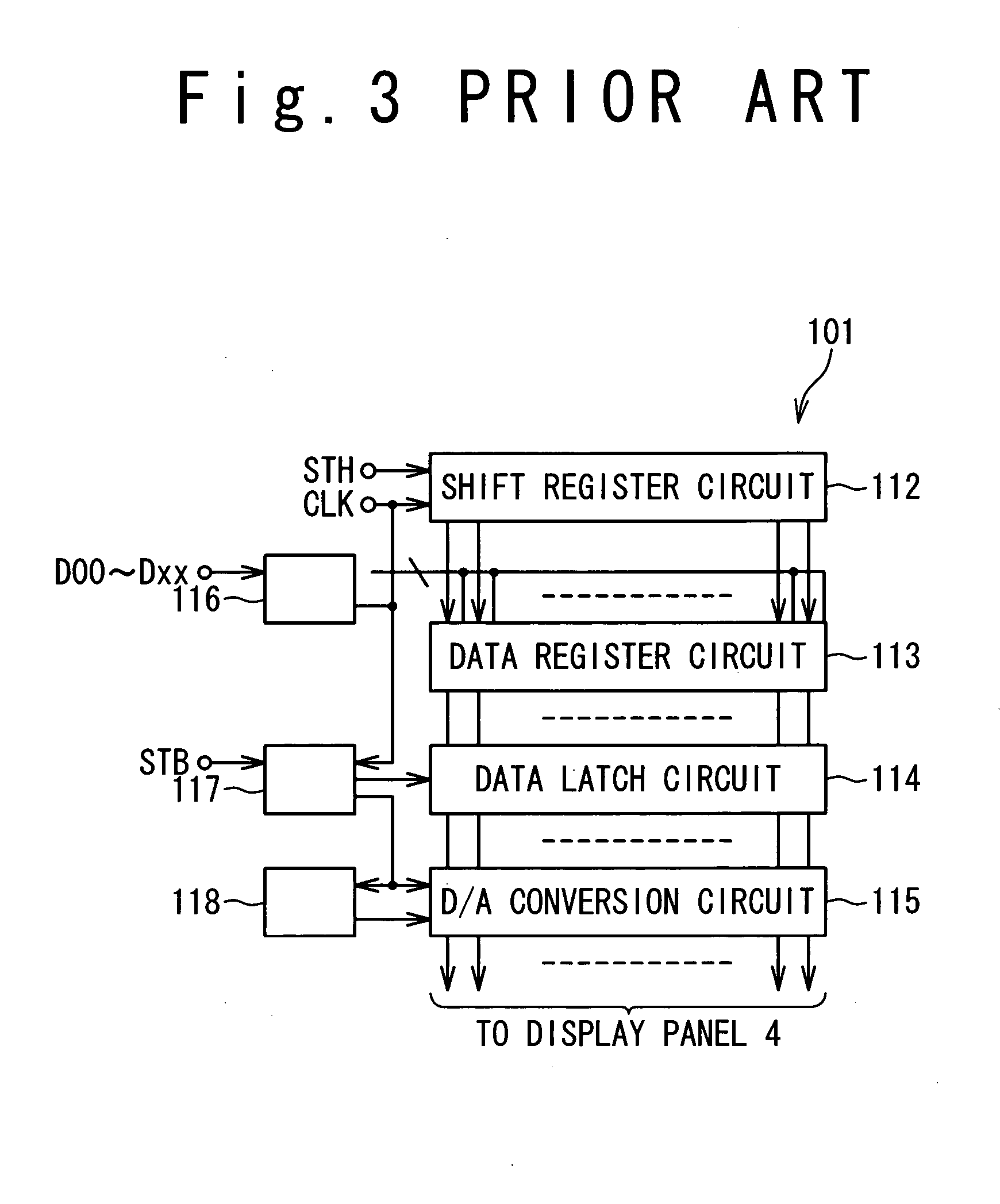
In addition, power consumption becomes large in an interface between the control circuit 103 and the data line driving circuit 101 because the number of bits is increased.
As a result, it is difficult to drive the data line in a low current level.
Therefore, if the data line driving circuit is formed on the glass substrate, ununiform display tends to be generated easily.
Forming the data line driving circuit 101 on the silicon substrate, it is difficult that the quasi-addition circuit 153 included in the data line driving circuit 101 has the same characteristic as the pixel 105 formed on the glass substrate, resulting in decrease in the reliability of the circuit.
Furthermore, when a switching is carried out from the voltage drive to the current drive, glitch is generated sometimes in the conventional display apparatus 100.
The glitch causes lowering image quality, especially in a low brightness (low current region) because a voltage is drifted from a desired voltage, even if the voltage is precharged to a desired voltage at high speed by the voltage driver.

Method used


Image

  • Display apparatus, and driving circuit for the same
  • Display apparatus, and driving circuit for the same
  • Display apparatus, and driving circuit for the same

Examples


first embodiment

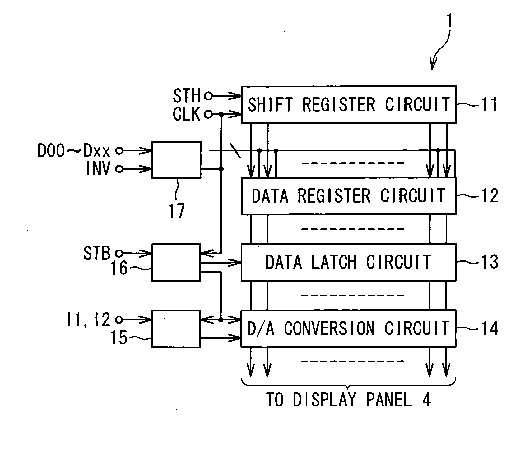
[0081]FIG. 5 is a block diagram showing the circuit configuration of a display panel apparatus according to the first embodiment of the present invention. As shown in FIG. 5, the display apparatus 10 includes a data line driving circuit 1, a scanning line driving circuit 2, a control circuit 3, and a display panel 4. The display panel 4 has a plurality of data lines 6 arranged in a column direction. Each data line 6 is connected with the data line driving circuit 1. Similarly, the display panel 4 has a plurality of scanning lines 7 arranged in a row direction. Each scanning line 7 is connected with the scanning line driving circuit 2. In addition, the display panel 4 has a pixel 5 at each of the intersections of the plurality of data lines 6 and the plurality of scanning lines 7.

[0082] The display apparatus 10 shown in FIG. 5 is driven by the sequential line driving method. The scanning line driving circuit 2 drives the plurality of scanning lines 7 in a predetermined order in resp...

second embodiment

[0130] The second embodiment of the present invention will be described below. FIG. 23 is a block diagram showing the configuration of a D / A conversion circuit 14a in the second embodiment of the present invention. As shown in FIG. 23, the D / A conversion circuit 14a in the second embodiment includes a first switch 61, a second switch 62, and a capacitor 63 in addition to the configuration of the above-mentioned D / A conversion circuit 14. The first switch 61 is connected between the node N1 and the input of the voltage driver 26. The capacitor 63 is connected between the input of the voltage driver 26 and the ground potential. The voltage driver 26, the first switch 61 and the capacitor 63 configure a sample-hold circuit. Also, the second switch 62 is connected between the node 1 and the current driver 28.

[0131] An operation of the D / A conversion circuit 14a shown in FIG. 23 will be described below. The D / A conversion circuit 14a turns the first switch 61 off immediately before the ...

third embodiment

[0133] The third embodiment of the present invention will be described below. FIG. 24 is a block diagram showing the configuration of a gradation voltage generating circuit 15a in the data line driving circuit 1 according to the third embodiment of the present invention. As shown in FIG. 24, the gradation voltage generating circuit 15a in the third embodiment includes a first gradation setting register 71, a second gradation setting register 72, a multiplexer 73, and a gradation voltage generator 74. The first gradation setting register 71 is a memory circuit to store the first gradation setting data for the plurality of first gradation voltages. Similarly, and the second gradation setting register 72 is a memory circuit to store the second gradation setting data for the plurality of second gradation voltages. The multiplexer 73 selects one of the gradation setting data stored in the first gradation setting register 71 and the second gradation setting register 72, and outputs the se...


PUM


Abstract

A drive circuit for a display apparatus includes a gradation voltage generation circuit and a D / A conversion circuit. The gradation voltage generation circuit generates a plurality of different first gradation voltages and a plurality of different second gradation voltages. The D / A conversion circuit drives a light emitting element of a pixel through a data line with a gradation voltage based on one of the first gradation voltages as a first specific gradation voltage in a precharge period and drives the light emitting element of the pixel through the data line with a gradation current based on one of the second gradation voltages as a second specific gradation voltage. The D / A conversion circuit includes a voltage driver to drive the light emitting element, and a current driver to drive the light emitting element.

Description

BACKGROUND OF THE INVENTION [0001] 1. Field of the Invention [0002] The present invention relates to a display apparatus such as a flat-panel display apparatus, a driving circuit for the display apparatus, and a semiconductor device for the driving circuit. [0003] 2. Description of the Related Art [0004] The importance of an apparatus to mediate a man or woman and a machine (man-machine interface) has been increased with the advance of computer technology. Especially, a display apparatus as one of the man-machine interfaces on the output side is required to have higher performance. The display apparatus displays data outputted from a computer for a man to visibly recognize the data. Various kinds of display apparatuses are commercially available. A typical display apparatus is a flat-panel display and is widespread. [0005] The flat-panel display apparatus is exemplified by a liquid crystal display and an organic electro-luminescence display apparatus using organic electro-luminescen...

Claims


Application Information

Patent Timeline
IPC IPC(8): G09G3/20H01L51/50G09G3/30G09G3/32H05B33/14
CPCG09G3/3233G09G3/3283G09G3/3291G09G2320/0276G09G2310/0251G09G2310/027G09G2300/0842G09G3/30G09G3/20
Inventor HASHIMOTO, YOSHIHARUYONEYAMA, TERU
Owner RENESAS ELECTRONICS CORP
Learn More