
Method for determining a level of material with a two-wire radar sensor comprising intermittently operating circuitry components and a two-wire radar sensor

Active Publication Date: 2005-08-04
VEGA GRIESHABER GMBH & CO
View PDF27 Cites 43 Cited by
  • Summary
  • Abstract
  • Description
  • Claims
  • Application Information

AI Technical Summary

Benefits of technology

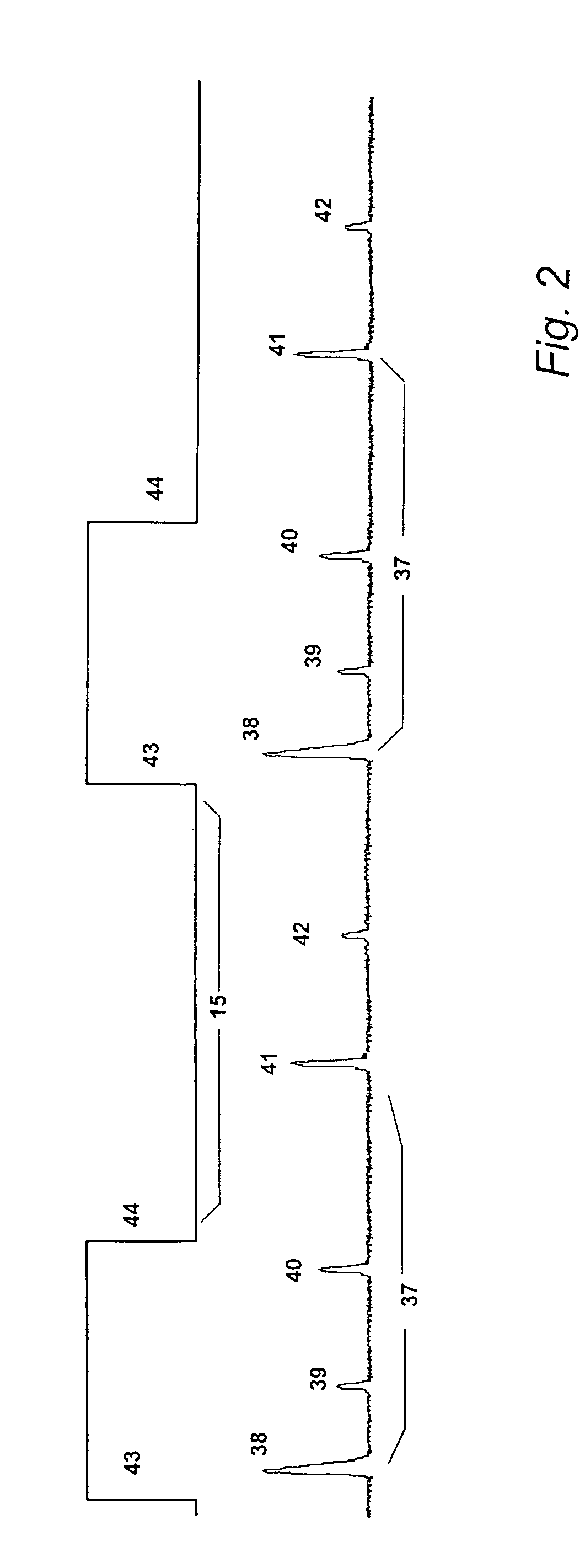
[0018] By subdividing the first measurement phase, during which the power consumption of the sensor is at a maximum, into at least two shorter partial phases, it is possible, to also use small energy stores which can cover the power consumption of the sensor at any time, and thus, allow for a two-wire control operation. The discharge of the energy store in the partial phases is not that high due to the shortened time period of a partial phase compared to the total first phase. The subsequent second or even third phases, being characterized by a low power consumption, enable a recharge of the energy store. The problem existing in prior art, to not be able to interrupt the first phase of a measurement, is solved by generating the constant reference echo at the beginning of each partial phase again.

Problems solved by technology

However, two-wire control loops are limited in providing sufficient energy for the measuring devices used in the field.
For the two-wire control operation of such an improve sensor, however, the problem arises that the power consumption will rise dramatically during the first phase of measurement.
By extension of the second phase, it could, however, be provided for the average power consumption not exceeding the limit set by the two-wire control, but for covering the comparatively high power consumption in the first measuring phase, large energy stores would be necessary, which cannot be united with circuit miniaturization.
If a large measuring range and a high dilation factor are used, then, a comparatively long time period results, during which a high power consumption has to be covered without any interruptions.

Method used


Image

  • Method for determining a level of material with a two-wire radar sensor comprising intermittently operating circuitry components and a two-wire radar sensor
  • Method for determining a level of material with a two-wire radar sensor comprising intermittently operating circuitry components and a two-wire radar sensor
  • Method for determining a level of material with a two-wire radar sensor comprising intermittently operating circuitry components and a two-wire radar sensor

Examples


Embodiment Construction

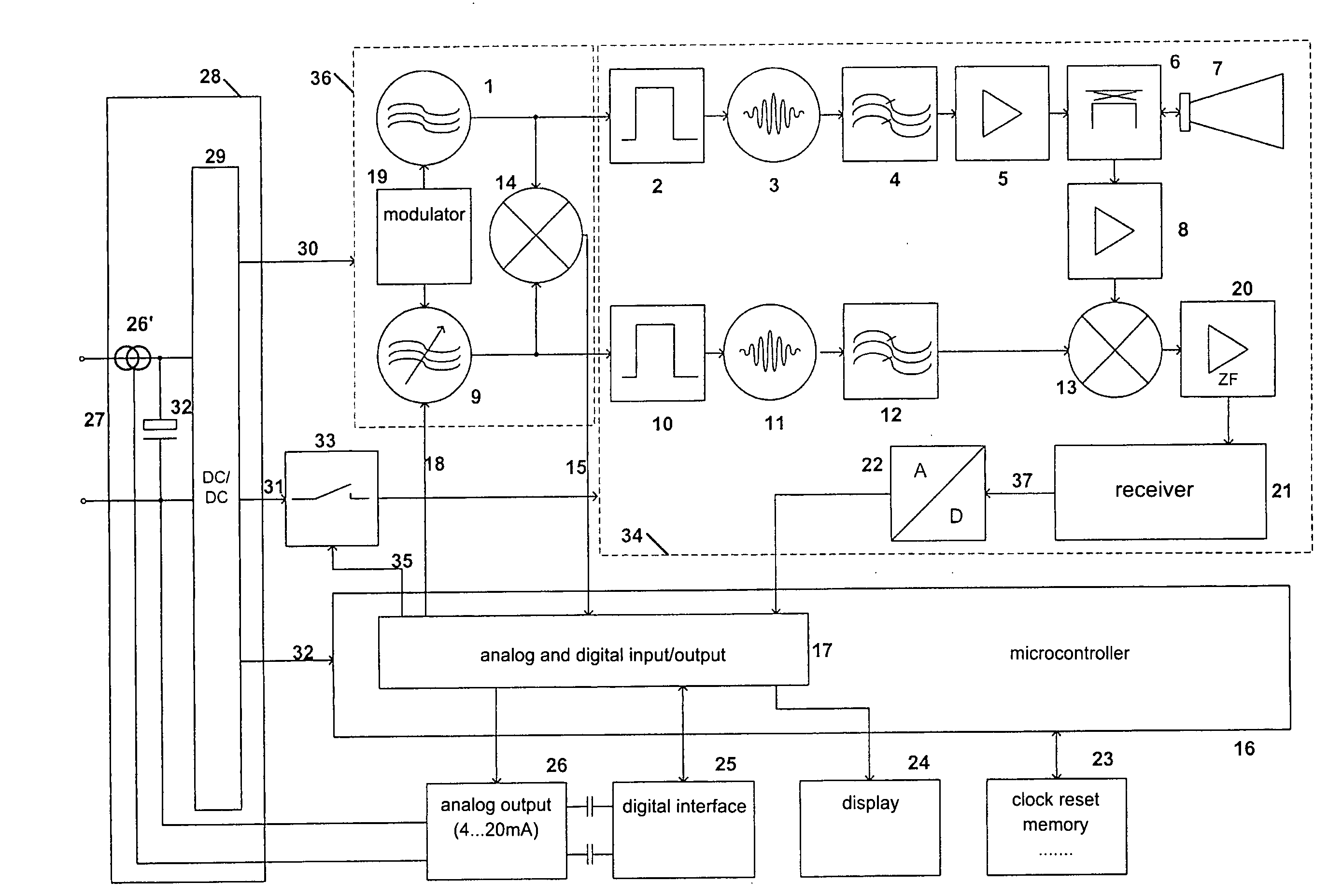
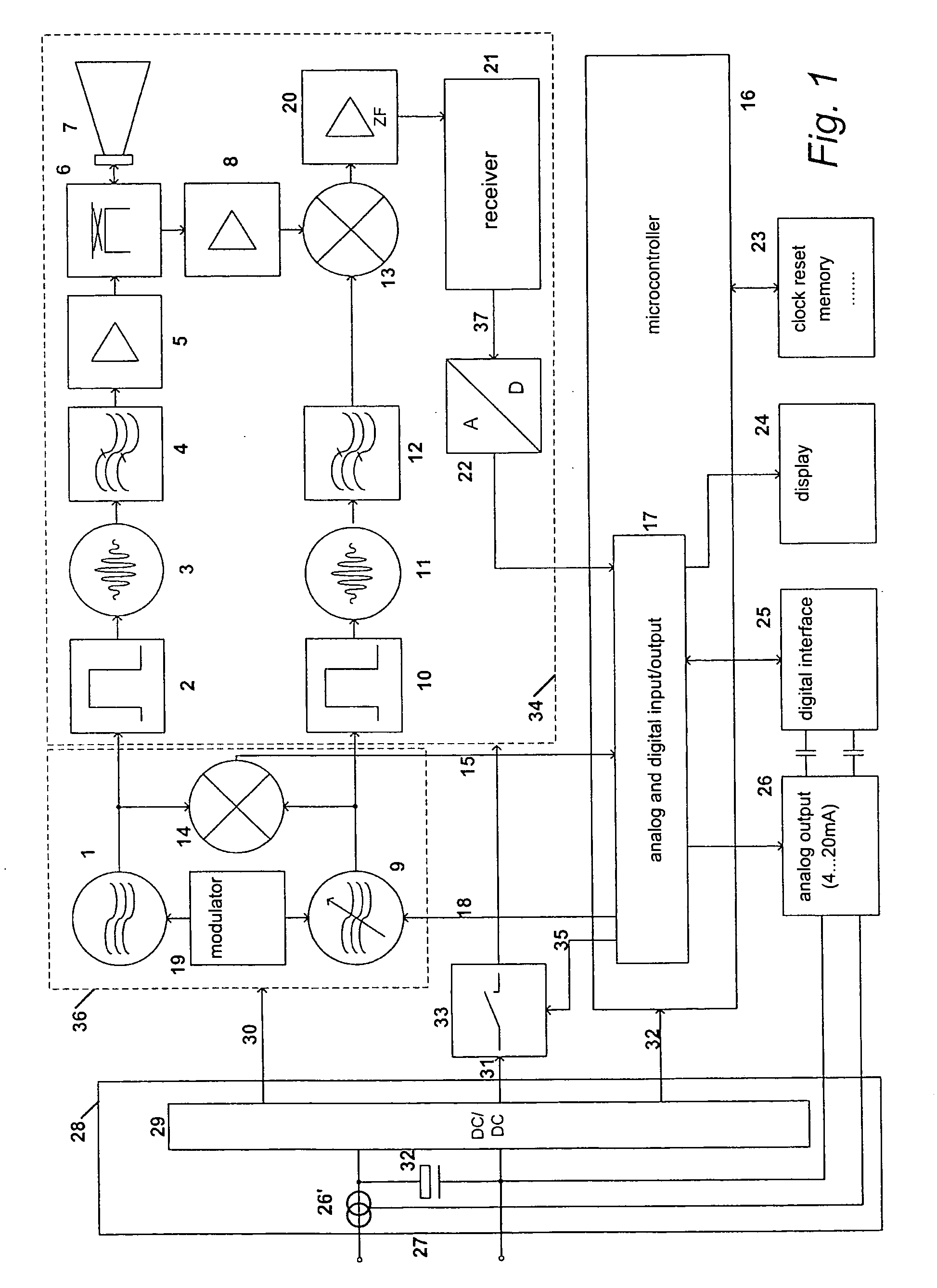
[0065]FIG. 1 shows a block diagram of a radar sensor for determining a level of material in a container, being known in prior art to a large extent already. A stable oscillator 1, e.g. a quartz oscillator, generates a transmission clock pulse, triggering a microwave pulse generator 3 for generating a transmission pulse via a slope steepening pulse former 2. After filtering through a bandpass filter 4, and amplification in amplifier 5, the transmission pulse is directed by the directional coupler 6 to antenna 7. After receipt of the reflected transmission pulse, this receipt pulse is coupled by antenna 7 via directional coupler 6 to the amplifier 8 (low noise amplifier).

[0066] The tunable oscillator 9, e.g. also a quartz oscillator, generates a sampling clock pulse, triggering a microwave pulse generator 11 via the pulse former 10. These microwave sampling pulses are directed via the bandpass filter 12 to the input of mixer 13. At the other input of the mixer 13, there is the amplif...


PUM


Abstract

A method for determining a distance between a radar sensor and a reflection surface of a material comprising the following steps. The radar sensor is energized via a two-wire control loop which allows for data communication and an internal energy store. An echo profile is generated and analyzed to calculate the distance. During generation of the echo profile, the generation process is interrupted at least once to recharge the energy store via the two-wire control loop.

Description

PRIORITY CLAIMS [0001] This application claims the benefit of U.S. Provisional Patent Application Ser. No. 60 / 542 066 filed on Feb. 04, 2004 which application is expressly incorporated herein, in its entirety, by reference.TECHNICAL FIELD OF THE INVENTION [0002] The invention relates to a method for determining a distance between a sensor and a reflecting surface of a material, to derive a level of material in a container by using a two-wire radar sensor with intermittently operating circuitry components. Moreover, the invention relates to a two-wire radar sensor to carry out the method. [0003] Two-wire radar sensors, to which the invention is applicable, are radar sensors being equipped with a two-wire control loop, providing for the power supply as well as for data communication. Further, the inventive method of determining a distance between a radar sensor and a reflecting surface of a material refers to the pulse radar technique. For this kind of measurement, a radar sensor is e...

Claims


Application Information

Patent Timeline
IPC IPC(8): G01F23/22G01F23/284G01S7/03G01S13/08G01S13/10G01S13/88
CPCG01F23/284G01S7/003G01S13/88G01S13/10G01S13/103G01S7/032
Inventor GRIESSBAUM, KARLRAUER, WINFRIEDFEHRENBACH, JOSEF
Owner VEGA GRIESHABER GMBH & CO
Learn More