
Plant and method for the treatment of the recovery cooling fluid in mechanical processing plants

a technology for mechanical processing plants and recovery cooling fluids, which is applied in the direction of gravity filters, feed/discharge of sedimentation settling tanks, gravity filters, etc., can solve the problems of clogging of the cartridge, plants having difficulty in operating well, and affecting the efficiency of cooling, so as to reduce idle times and increase productivity.

Active Publication Date: 2005-08-04
P M P O
View PDF98 Cites 17 Cited by
  • Summary
  • Abstract
  • Description
  • Claims
  • Application Information

AI Technical Summary

Benefits of technology

[0031] Thanks to this, the washing operation of the filters takes place at much longer time intervals than those according to the prior art, with substantial elimination of the idle times caused by it, and consequent increased productivity.

Problems solved by technology

The solid material contained in the liquid remains lodged inside the cartridge where it forms a layer that must be periodically removed, since as it increases in thickness it progressively clogs up the cartridge.
It has been noted that known plants have some difficulty in operating well when the residual liquids of fine processing are treated, like the aforementioned lapping.
In these cases, indeed, the size of the chip particles is in the order of between 0.1 and 7.0 microns, and the mud not only tends to clog up the filtering cartridge very quickly, but the washing operation carried out in the conventional way is not sufficient to restore the characteristics of the cartridge.

Method used


Image

  • Plant and method for the treatment of the recovery cooling fluid in mechanical processing plants
  • Plant and method for the treatment of the recovery cooling fluid in mechanical processing plants
  • Plant and method for the treatment of the recovery cooling fluid in mechanical processing plants

Examples


second embodiment

[0173] Using a second tubular body 20112 in the variant embodiment just described allows the sieve layer 2014 to be used (not illustrated for the sake of simplicity).

[0174] Such a second embodiment is given by a sieve layer 2014 not stitched longitudinally.

[0175] Such an unstitched sieve layer 2014 is obtained from a substantially rectangular portion of fabric, unwoven fabric, metallic mesh or similar (or combinations of such materials) arranged adjacent to the inner surface 11a inside the first tubular body 11 with its unwoven longitudinal lips overlapping.

[0176] Once the layer 2014 with overlapping lips is arranged adjacent to the inner surface 2011a, the second tubular body 2112 is inserted in the variant embodiment described above.

[0177] Such a second tubular body 2112, not yet locked by the clamping of the nut 2132 to the threaded element 2133, dilating and increasing its diameter, compresses the layer 2014 against the first tubular body 2011.

[0178] The layer 2014, although ...

first embodiment

[0185] The double suction submerged pump structure in a first embodiment thereof is wholly indicated with reference numeral 3010.

[0186] Such a structure 3010 comprises, in a protective containment casing, a rotation shaft 3012 on which a pair of opposite interfacing suction impellers 3013 is fitted inside a chamber 3014, for such impellers 3013, for conveying the fluid towards a delivery 3015.

[0187] The shaft 12, actuated at the top end 3016 by a motor (not illustrated for the sake of simplicity), is rotatable on rotational sliding means 3018.

[0188] First fluidic sealing means 3038 are associated with such a shaft, arranged between the motor and the chamber 3014. Such a submerged pump structure 3010 has, below the pair of suction impellers 3013, a hollow tang defining a seat 3020 for the bottom end 3019 of the shaft 3012.

[0189] Such a hollow tang is integral with the casing 3011. Between the shaft 12 and the hollow tang 3020 the rotational sliding means 3018 and corresponding sec...


PUM

PropertyMeasurementUnit
pressureaaaaaaaaaa
pressure impulsesaaaaaaaaaa
sizeaaaaaaaaaa

Abstract

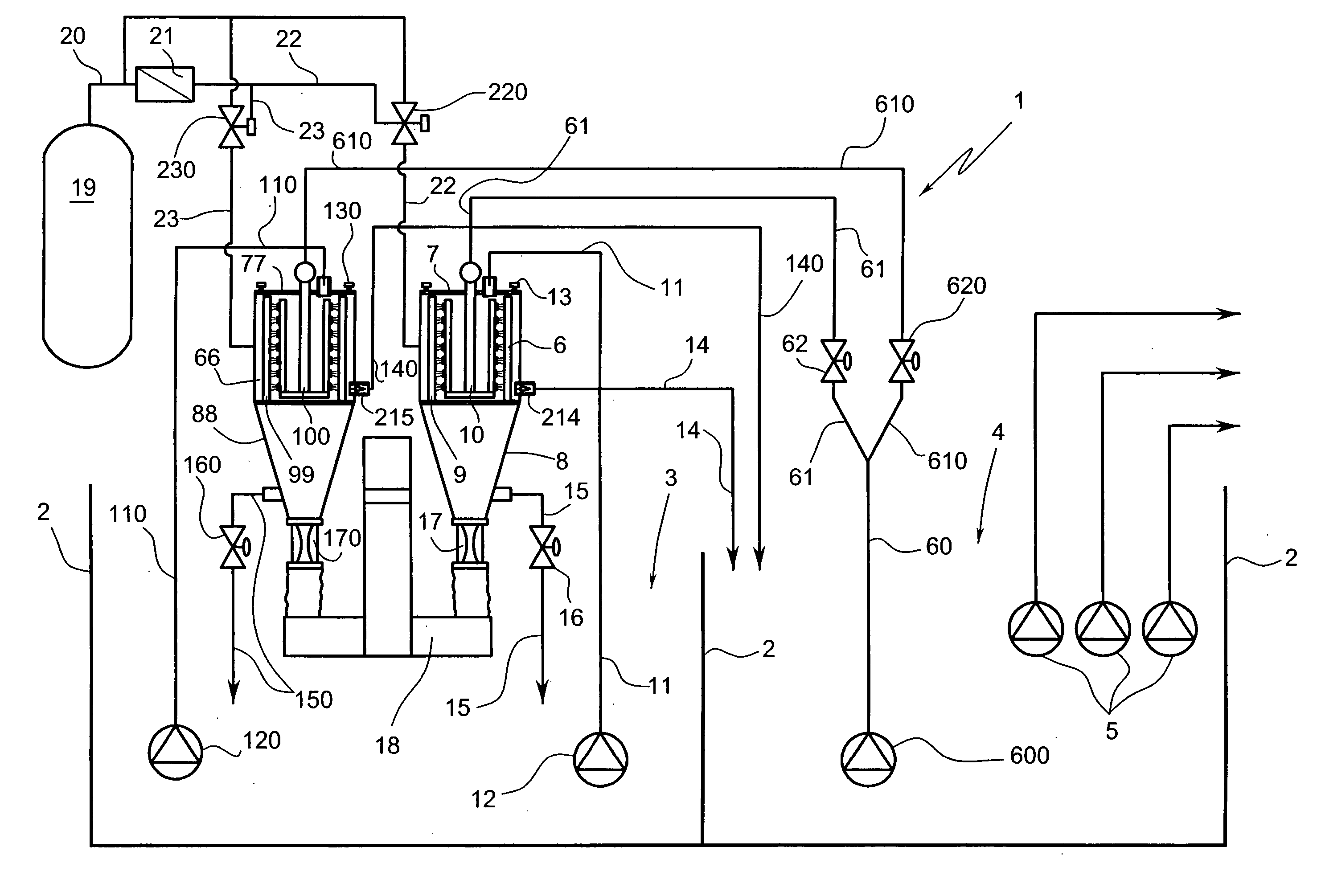
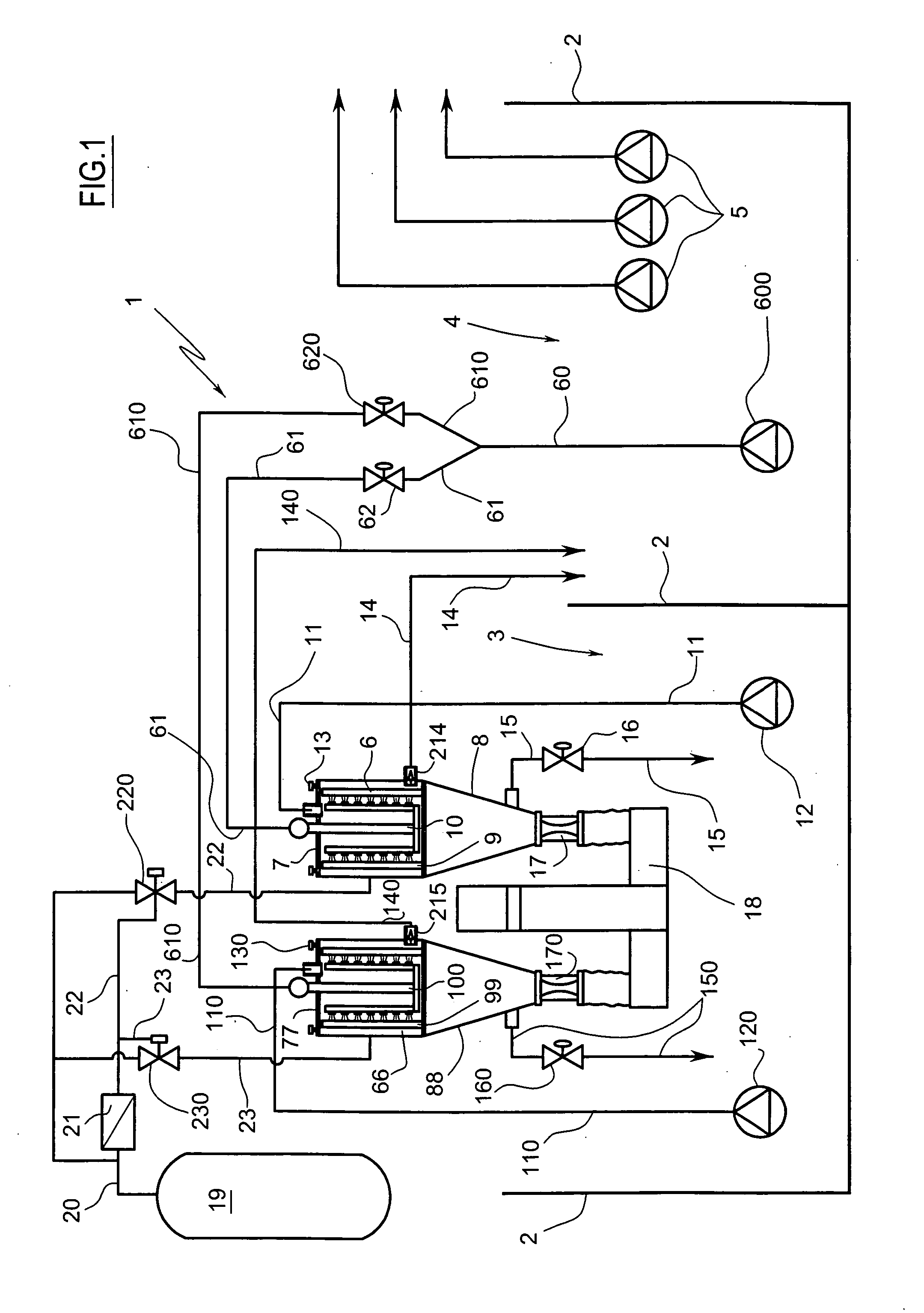
Plant for treating the leftover liquids of mechanical processing, comprising a filtering partition (9) for filtration of the fluid and means for cleaning the partition by washing of the layer of mud deposited hereon, comprises vibratory means suitable for causing a generally fast and continuous vibratory state at least in the active portion of the partition. The plant comprises at least one chamber (6) that is divided into two parts by the filtering partition (9), one part being intended for the exit of the filtered fluid, means suitable for causing a generally fast and continuous vibratory state at least in the active portion of the partition are associated with said chamber. Method for treating the leftover fluids of mechanical processing, comprising filtration of the fluid through a filtering partition and periodic cleaning of the partition through washing of the layer of mud deposited here; it foresees that at least the surface of the partition on which the mud deposits is subjected to vibratory motion.

Description

TECHNICAL FIELD [0001] The present invention refers to the treatment of recovery waters used, sometimes suitably additived, as a cooling fluid in mechanical processing plants for chip removal. BACKGROUND ART [0002] In general the treatment is not limited to recovery fluid of mechanical processing, but is also carried out to recover residual liquids of other types of processing. The treatment of said waters is made necessary by a series of reasons. [0003] A first reason is of the ecological type, and requires that the muds that form in said waters be separated to allow recycling or else discharge thereof into the environment. [0004] A second reason is of the economic type, since a substantial amount of processing chips are contained in the muds, and when the worked piece is made from a valuable material this implies a need to recover the chips. [0005] A third reason is the perfect and complete separation of the material filtered from the treated liquid. [0006] A last but not least re...

Claims


Application Information

Patent Timeline
Patent Type & Authority Applications(United States)
IPC IPC(8): B01D29/11
CPCB01D29/111B01D2201/0415B01D2201/291B01D29/23B01D29/6438B01D29/661B01D29/72
Inventor PANCALDI, FABIOGALLOCCHIO, VANNI
Owner P M P O
Learn More