Resin hose with resin reinforcing wire rod

a technology of reinforcing wire rods and resin hoses, which is applied in the direction of transportation and packaging, separation processes, and other domestic objects, can solve the problems of deterioration of the strength of air bubble containing portions, easy to check visually whether the wire rod contains air bubbles from an exterior view of the wire rod, and deterioration of the predetermined pressure flat strength, etc., to achieve excellent pressure flat strength, reduce the effect of strength

Inactive Publication Date: 2005-07-28
TOTAKU IND INC
View PDF5 Cites 7 Cited by
  • Summary
  • Abstract
  • Description
  • Claims
  • Application Information

AI Technical Summary

Benefits of technology

[0010] Therefore, in order to overcome such subject involved in a resin reinforcing wire rod in the related-art resin tube, it is an object of the present invention to obtain a resin tube with a resin reinforcing wire rod, capable of reducing generation of air bubbles by devising a shape of the wire rod and also capable of checking easily the presence or absence of the air bubbles from the outside with the eye.
[0012] The resin tube with the resin reinforcing wire rod of the present invention is constructed to have such a structure that the reinforcing wire rod 2 is formed of the transparent or semitransparent member made of the rigid synthetic resin and also the sectional shape of the reinforcing wire rod 2 has the recess 3 in the cross section. Thus, the outer peripheral shell formed when the surface of the wire rod is cooled and solidified does not become the complete one, and thus is shaped into the sectional shape a part of which is lost. Therefore, the outer peripheral shell is shrunken subsequently to the shrinkage of the internal volume due to the crystallization of the material caused by the gradual cooling that proceeds gradually inwardly, etc., and thus the pressure in the inner side is never lowered. As a result, neither the volatile component contained the material is vaporized nor the gas at the ultra fine state is expanded, so that the wire rod containing no air bubble and having a clear external appearance can be obtained.
[0013] The resin reinforcing wire rod obtained in this manner to contain no air bubble has a desired strength uniformly in the overall wire rod. Therefore, the wire rod of uniform quality, in which neither the strength is lowered partially or locally owing to the presence of the contained air bubbles nor the weak portions acting to cause the generation of cracks are generated, can be manufactured. As a result, the tube member reinforced by such wire rod is excellent in the pressure flat strength, and thus such tube member can be used safely for a long term as the tube that has the less time-dependent degradation.
[0014] In addition, the wire rod itself is formed as the transparent member or the semitransparent member into which the coloring agent is added. Therefore, the presence or absence of the air bubbles can be checked easily from the outside and also the machine can be immediately repaired / adjusted when the air bubbles are generated in the wire rod at the time of production. As a result, there can be achieved such an advantage that the excellent wire rod that contains no air bubble therein can be always produced.

Problems solved by technology

However, most of these reinforcing wire rods made of the rigid synthetic resin are rendered opaque by mixing a coloring agent into the resin material.
In the related art, by manufacturing the reinforcing wire rod as opaque one, even though the air bubbles are generated in the inside, it is hard to check easily and visually whether or not the wire rod contains the air bubbles from an exterior view of the wire rod.
In the case where the resin reinforcing wire rod contains the air bubbles, deterioration in a predetermined pressure flat strength is brought about, particularly the strength of the air bubble containing portions is deteriorated, and also such air bubbles act as the cause or the distant cause of generation of the crack.
However, it is the existing state of the resin reinforcing wire rod in resin tube materials of this type that particular attention, studies and concernment to satisfy the above necessities are not taken into account at all.

Method used


Image

  • Resin hose with resin reinforcing wire rod
  • Resin hose with resin reinforcing wire rod
  • Resin hose with resin reinforcing wire rod

Examples


examples

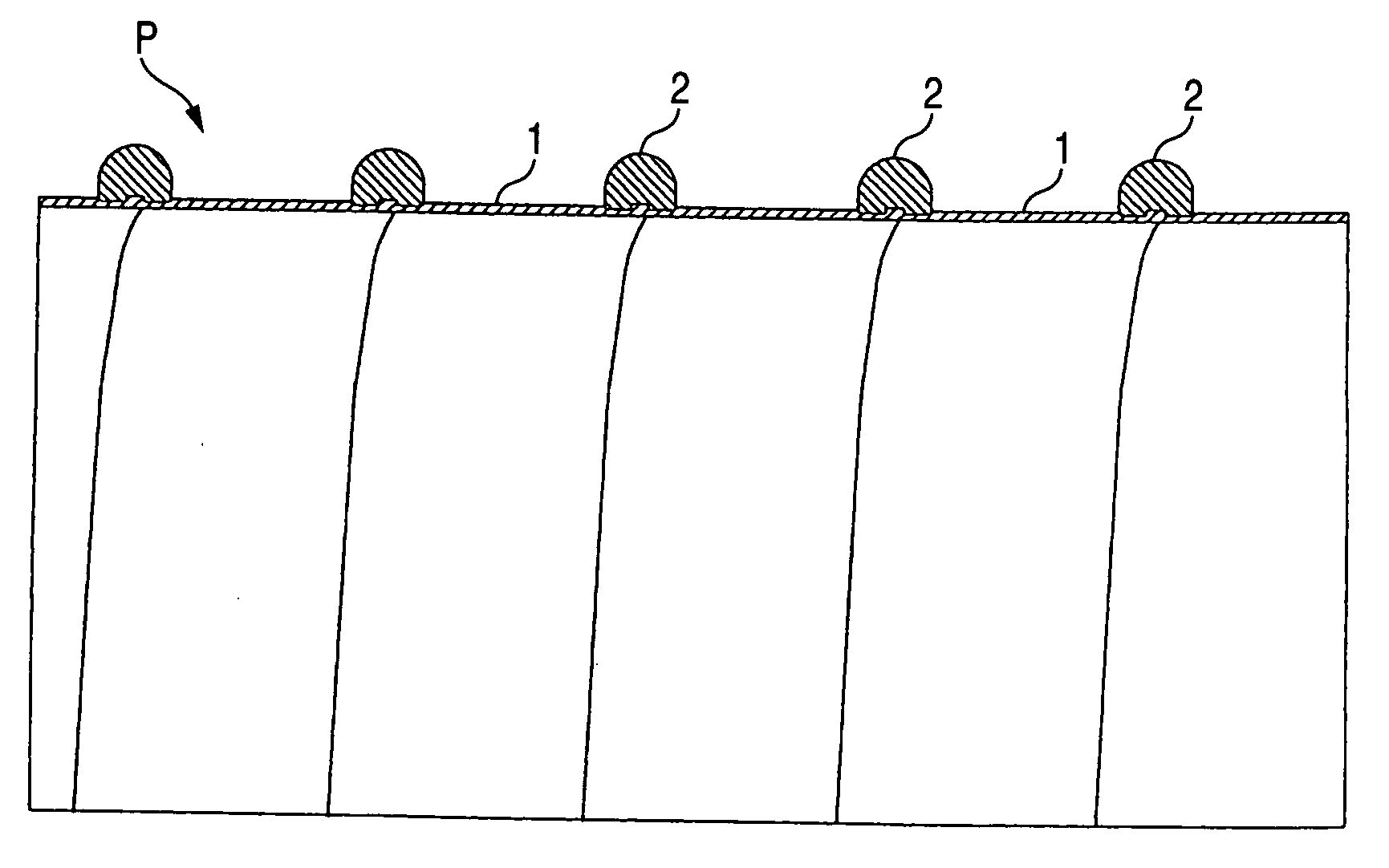
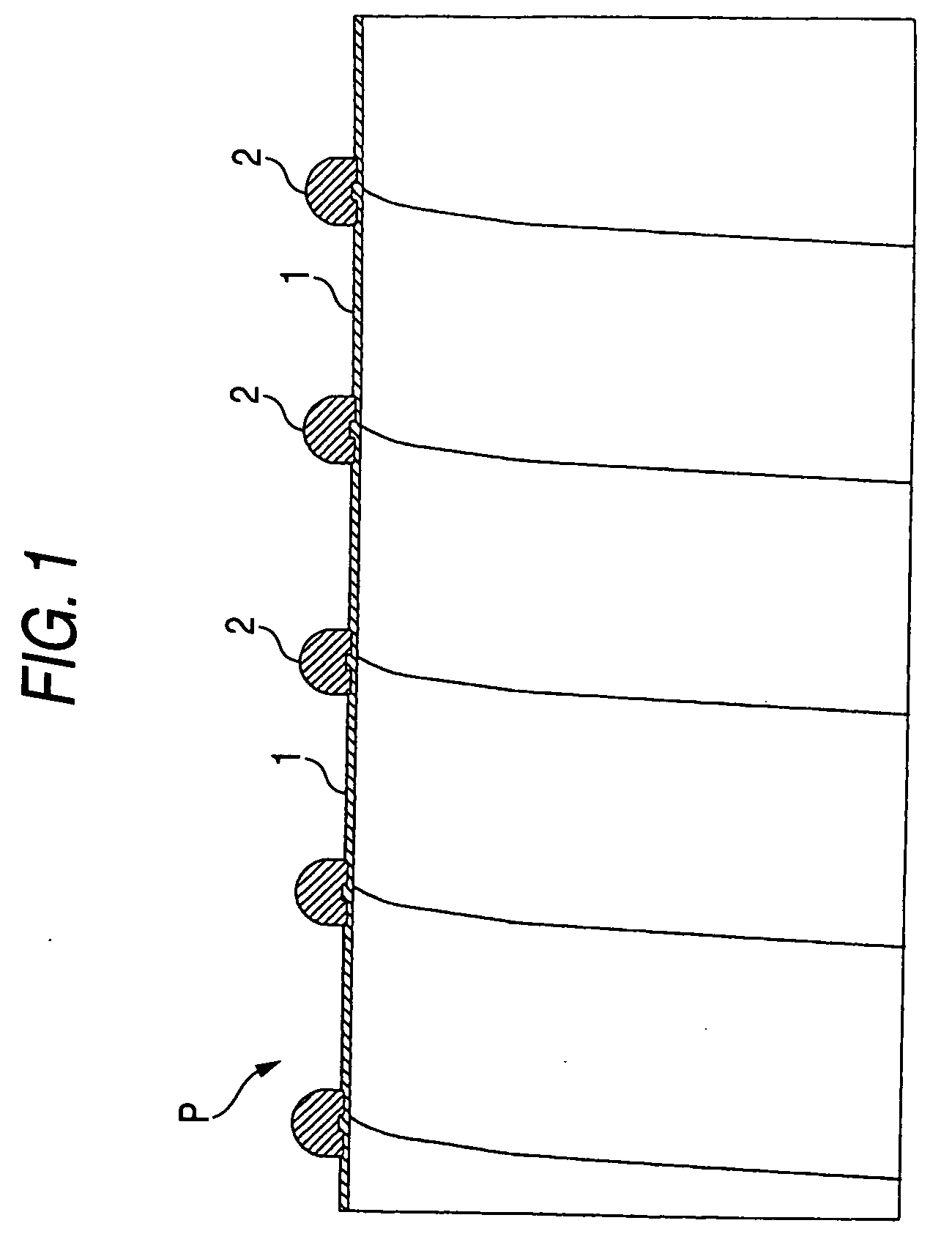
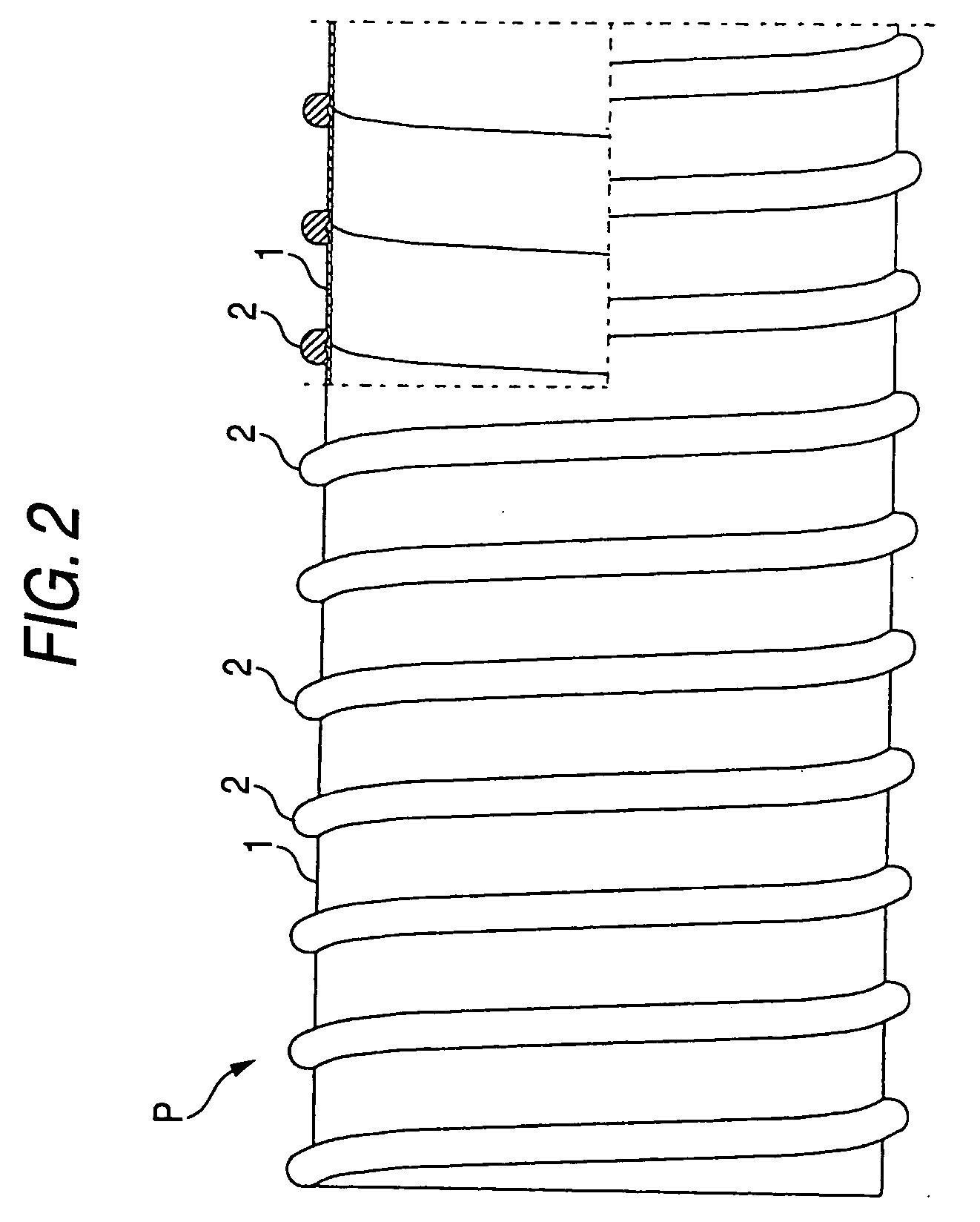
[0023] Examples of the present invention will be explained with reference to the drawings hereinafter. In Figures, FIG. 1 to FIG. 4 are views showing main embodiments of the present invention. More specifically, FIG. 1 is a partial sectional view of a tube member showing a relationship between a tube wall and a wire rod, FIG. 2 is a front view of the tube member from which the tube wall is partially cut away, FIG. 3 is a perspective appearance view showing a shape of the wire rod, and FIG. 4 is a sectional view of the same wire rod.

[0024] A tube member P shown in FIG. 1 and FIG. 2 is constructed such that a tube wall 1 is formed cylindrically by winding helically a strip material in such a way that its side edge portion is overlapped partially with each other and is fused mutually, while extruding the material from a resin extruder (not shown). The strip material is made of olefin elastomer and has a sectional shape formed in a lateral straight line.

[0025] Then, a wire rod 2 forme...


PUM

PropertyMeasurementUnit
Transparencyaaaaaaaaaa

Abstract

In a resin tube that comprises a cylindrical tube wall made of synthetic resin material, and a resin reinforcing wire rod that is wound helically on an outer peripheral surface of the tube wall and coupled integrally, the reinforcing wire rod is formed of a transparent or semitransparent member made of rigid synthetic resin and has a recess that is formed on a part of the outer peripheral surface in the longitudinal direction.

Description

[0001] This application claims foreign priority based on Japanese patent application JP 2004-003724, filed on Jan. 9, 2004, the contents of which is incorporated herein by reference in its entirety. BACKGROUND OF THE INVENTION [0002] 1. Field of the Invention [0003] The present invention relates to a synthetic resin tube on which a reinforcing wire rod made of rigid synthetic resin is helically wound to maintain a tubular shape and reinforce the tube. More particularly, the present invention relates to a synthetic resin tube with a reinforcing wire rod, which employs a transparent wire rod as the reinforcing wire rod made of the rigid synthetic resin. [0004] 2. Description of the Related Art [0005] In the related art, as the synthetic resin tubes having the reinforcing wire rod made of the rigid synthetic resin of this type, the synthetic resin tubes having various shapes have already been manufactured and well known commonly. However, most of these reinforcing wire rods made of the...

Claims


Application Information

Patent Timeline
IPC IPC(8): B32B1/08F16L11/10F16L9/12F16L9/128F16L11/115
CPCB32B1/08Y10T428/1393F16L11/115B01D46/0005B01D46/10B32B27/08B32B2307/50B32B2307/718B32B2597/00
Inventor TAKASHIMA, MASATOSHIHORII, TOMOHIDENAKAMATA, KEIJI
Owner TOTAKU IND INC
Why Eureka
Try Eureka