Flat type fluorescent lamp

a fluorescent lamp and flat-type technology, applied in the field of flat-type fluorescent lamps, can solve the problems of limited inability to achieve constant light emission and brightness on the whole surface, and inability to reduce the thickness of plate-type spacers, so as to improve light emission efficiency and brightness, remove non-light emission areas, and expand light emission areas

Inactive Publication Date: 2005-07-28
LEE KYE SEUNG
View PDF3 Cites 7 Cited by
  • Summary
  • Abstract
  • Description
  • Claims
  • Application Information

AI Technical Summary

Benefits of technology

[0010] It is an objective of the present invention to provide a flat type fluorescent lamp that is improved in its light emission efficiency and brightness by removing non-light emission area and enlarging light emission area by installing a tube spacer in an outer lamp body, thereby realizing the inventive surface light source.

Problems solved by technology

Although the above-described flat type fluorescent lamp is good for realizing the surface light source, since it has a non-light emission area, light emission and brightness cannot be constantly realized on the whole surface.
For example, since a plate type spacer is installed in the outer lamp body with the phosphor on the inner surface, the non-light emission area is inevitably formed as large as the thickness of the plate type spacer and there is a limitation in reducing the thickness of the plate type spacer.
Therefore, the conventional flat type fluorescent lamp has deteriorated brightness at a portion where the spacer is installed and excessive brightness at a portion where the spacer is not installed, resulting in a large amount of brightness difference and deteriorating the light emission efficiency in general.
However, since the diffuser is generally provided for the purpose of compensating for the uniformity by suppressing the light emission at the high brightness area, it deteriorates the overall light emission efficiency.
Therefore, there is a limitation in compensating for the brightness by the diffuser as the conventional flat type fluorescent lamp has a large amount of brightness difference.

Method used


Image

  • Flat type fluorescent lamp
  • Flat type fluorescent lamp
  • Flat type fluorescent lamp

Examples


embodiment 1

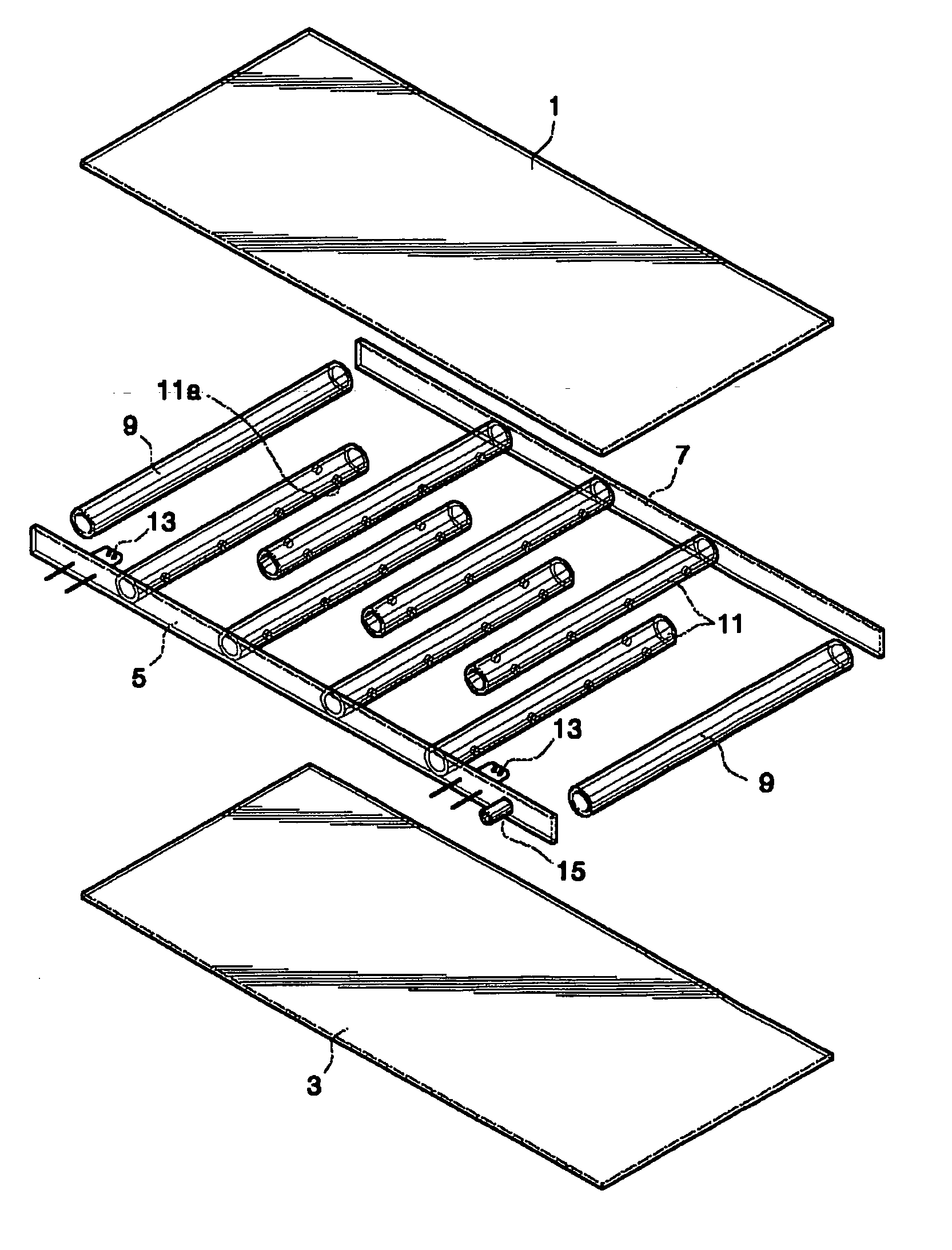
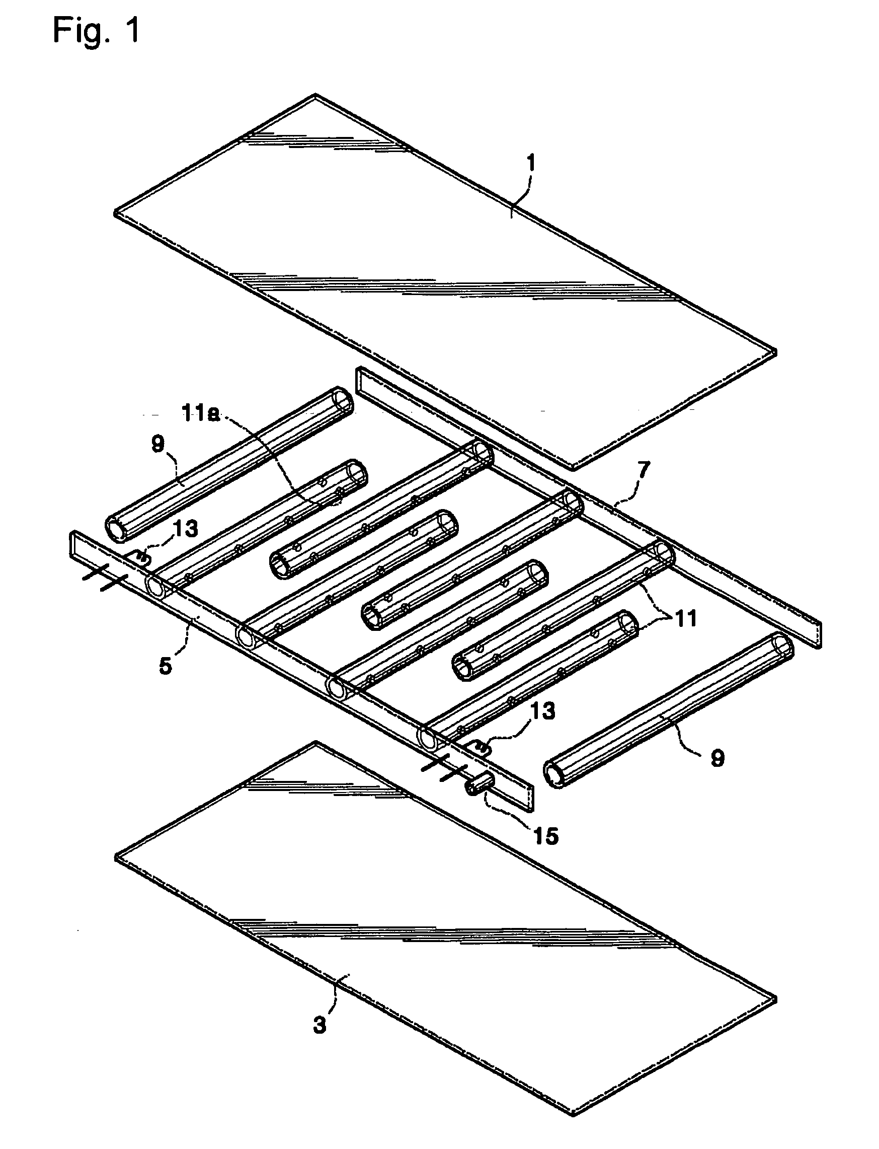
[0037]FIGS. 1 and 2 show a flat type fluorescent lamp according to a first embodiment of the present invention.

[0038] As shown in the drawings, the inventive flat type fluorescent lamp is defined by a rectangular parallelepiped outer lamp body for realizing a surface light source such as a backlight for a flat display and a lighting device.

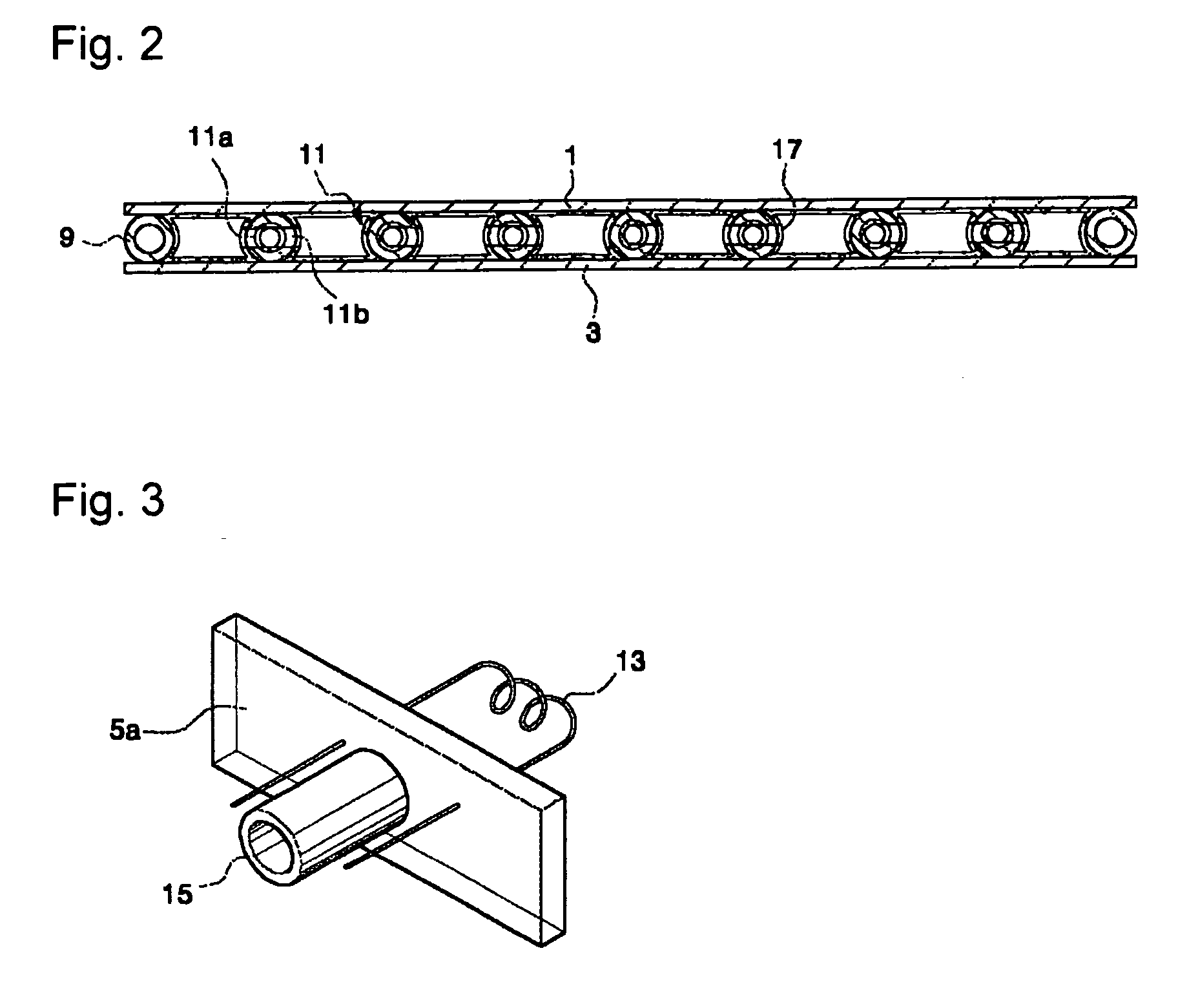
[0039] The outer lamp body comprises front and rear panels 1 and 3, and longitudinal and lateral seal members 5, 7, and 9 for sealing a space defined between the front and rear substrates 1 and 3. Here, the rear panel 3 and the seal members 5, 7 and 9 are formed of transparent or semi-transparent material. Moreover, a reflection layer may be formed on the rear panel 3.

[0040] In addition, the lateral seal members 9 may be formed of tube spacers. Each of the tube spacers 9 has a length identical to that of a width of the outer lamp body. The longitudinal seal members 5 and 7 may be formed of side plates.

[0041] As a feature of the invention, plur...

embodiment 2

[0060]FIGS. 6 and 7 show a flat type fluorescent lamp according to a second embodiment of the present invention.

[0061] As shown in the drawings, the inventive flat type fluorescent lamp of this embodiment includes an outer lamp body as in the first embodiment. As a feature of this embodiment, plural tube spacers 111 are disposed between the front and rear panels 1 and 3.

[0062] Each of the tube spacers 111 is designed shorter than the width of the outer lamp body. That is, the length of the tube spacer 11 is {fraction (1 / 10)}-½ of the width of the outer lamp body. The tube spacers 111 can be randomly disposed or aligned in lines. As in the first embodiment, a section of the tube spacer 111 can be designed in a variety of shapes such as a circular-shape, an oval-shape, or a polygonal-shape.

[0063] The above described structure and arrangement of the tube spacers 111 according to this embodiment allows the phosphor layer 17 to be more easily deposited to an inner surface of the outer...

embodiment 3

[0066] This third embodiment is identical to the first and second embodiment except that a phosphor layer 17 is further optimized to improve the light emission efficiency and the brightness.

[0067] That is, in this third embodiment, a thickness “d” of the phosphor layer 17 deposited on the inner surface of the outer lamp body is defined to satisfy the following range:

d=4logeW˜d=4logeW+16

where, W indicates electric power of the lamp.

[0068] Test results obtained by the above conditions are shown in Table 1 and FIG. 9. In the test, a three-wavelength phosphor is used as the phosphor material, and Y2O3:Eu, LaPO4:Ce,Tb, and (Sr,Ca,Ba)10(PO4)6C12:Eu are respectively used for red R, green G and blue B colors of the phosphor material. In addition, the phosphor has a mean particle size in a range of 2-10 μm and is deposited on 80±10% with respect to the entire surface area.

[0069] Alternatively, phosphor material used for a plasma display panel (PDP) can also be used as the phosphor. The...


PUM


Abstract

The present invention discloses a flat type fluorescent lamp that is improved in its light emission efficiency and brightness by installing a tube spacer between 2 panels. A flat type fluorescent lamp includes an outer lamp body comprising front and rear panels, and circumference seal members, and tube spacers installed in the outer lamp body to divide the discharge spaces in plural sections communicating with each other to define a discharge path, a phosphor layer deposited on the outer lamp body and the tube spacers, and a discharge electrode supported on the outer lamp body.

Description

TECHNICAL FIELD [0001] The present invention relates to a flat type fluorescent lamp and, more particularly, to a fluorescent lamp that is improved in its light emission efficiency and brightness by removing non-light emission area and enlarging light emission area by installing a tube spacer in an outer lamp body, thereby realizing the inventive surface light source. BACKGROUND ART [0002] A flat type fluorescent lamp is widely used as a backlight for a flat display panel as well as a lighting device, being increasingly increased in its application field. [0003] A conventional flat type fluorescent lamp comprises two glass substrates and a side plate, which are assembled to each other. Spacers are disposed between the glass substrates to constantly maintain a gap between the substrates, while providing a discharge path. A phosphor is deposited on an inner surface of an outer lamp body, and a discharge electrode is installed on both ends of the side plate. Air in the lamp body is exh...

Claims


Application Information

Patent Timeline
IPC IPC(8): H01J61/06H01J17/16H01J61/04H01J61/067H01J61/30H01J61/42
CPCH01J61/305
Inventor LEE, KYE SEUNG
Owner LEE KYE SEUNG
Why Eureka
Try Eureka