Torque sensor
- Summary
- Abstract
- Description
- Claims
- Application Information
AI Technical Summary
Benefits of technology
Problems solved by technology
Method used
Image
Examples
first embodiment
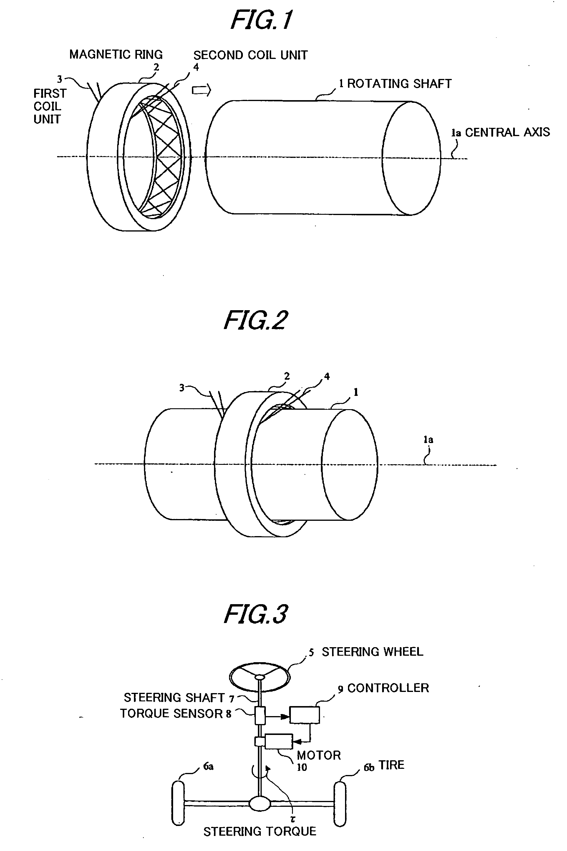
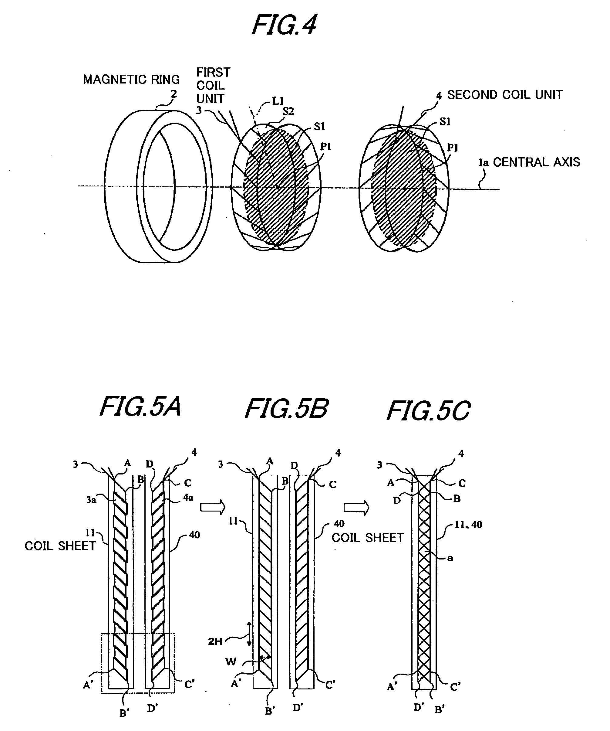
[0061]FIG. 1 is an exploded perspective view of an example of the construction of the torque sensor in the first preferred embodiment. As shown in FIG. 1, the torque sensor in the first embodiment can detect a torque in a rotating shaft 1 having magnetostrictive properties and not having any groove or the like on its surface.
[0062] The torque sensor in the first embodiment shown in FIG. 1 has a structure including a magnetic ring 2 which can be disposed on the outer circumference of the rotating shaft 1. A first coil unit 3 and a second coil unit 4 which are provided on an inscribed face of the magnetic ring 2. In order to measure the torque of the rotating shaft 1, the magnetic ring 2 on which the first coil unit 3 and the second coil unit 4 have been disposed should be disposed on the outer circumference of the rotating shaft 1.
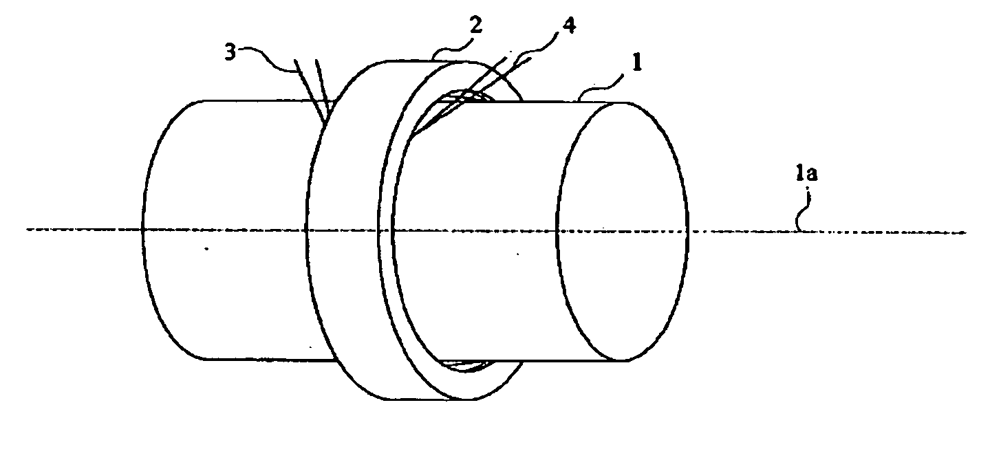
[0063]FIG. 2 is a diagram showing such a state that the magnetic ring 2 is disposed on the outer circumference of the rotating shaft. As shown in FIG. 2, ...
fourth embodiment
[0094]FIG. 13 is a diagram showing an example of the construction of the torque sensor in the As with the torque sensor shown in FIG. 11, the torque sensor in this embodiment can shorten the gap. The torque sensor in this embodiment is different from the torque sensor in the embodiment shown in FIG. 11 in that only one magnetic ring 2 is used and the first coil unit 16 and the second coil unit 17 are disposed on the inscribed face of the magnetic ring 2.
[0095]FIG. 14A is a diagram showing an example of the construction of a coil sheet 15 in which the first and second coil units 16, 17 have been developed. The first coil unit 16 and the second coil unit 17, in which the direction of two sides in the first coil unit 16 and the direction of two sides in the second coil unit 17 are +45 degrees and −45 degrees, respectively, are applied in series onto the coil sheet 15 in its longitudinal direction (vertical).
[0096] Winding of these coils shown in the drawing is the same as that in oth...
fifth embodiment
[0098]FIG. 15 is a diagram showing an example of the construction of a torque sensor in the fifth embodiment which can shorten the width of the torque sensor. As shown in FIG. 16, a magnetic ring 2, a first coil unit 18, and a second coil unit 19 constituting a detection part in FIG. 15 can be dismantled. FIG. 17A is a development diagram showing the first and second coil units 18, 19 shown in FIG. 16 which have been developed. The first coil unit 18 and the second coil unit 19 are applied to a coil sheet 20 and a coil sheet 21, respectively. As shown in FIG. 17B, these coil sheets 20, 21 are superimposed on top of each other, and the assembly is disposed on the inner face of the magnetic ring 2 shown in FIG. 15. The torque sensor in this embodiment is characterized in that, regarding substantially parallelogramatical coils constituted by the coil units 20, 21, the narrow angle of the parallelogram is 30 degrees rather than 45 degrees. According to this construction, regarding the f...
PUM
 Abstract
Description
Claims
Application Information
 - R&D
- Intellectual Property
- Life Sciences
- Materials
- Tech Scout
- Unparalleled Data Quality
- Higher Quality Content
- 60% Fewer Hallucinations
Browse by: Latest US Patents, China's latest patents, Technical Efficacy Thesaurus, Application Domain, Technology Topic, Popular Technical Reports.
© 2025 PatSnap. All rights reserved.Legal|Privacy policy|Modern Slavery Act Transparency Statement|Sitemap|About US| Contact US: help@patsnap.com


