
Driving status detection device and related method

a technology of status detection and status detection, which is applied in the direction of process control, instruments, and machines, etc., can solve the problems of no consideration of a condition without concentration and no detection of the structur

Inactive Publication Date: 2005-07-21
NISSAN MOTOR CO LTD
View PDF10 Cites 94 Cited by
  • Summary
  • Abstract
  • Description
  • Claims
  • Application Information

AI Technical Summary

Benefits of technology

[0007] The present invention has been completed upon conduction of the above studies by the present inventors and has an object to provide a driving status detection device and its related method that are able to detect driver distraction forming a risk occurrence scene in a more reliable manner.
[0008] Further, it is an object of the present invention to provide a driving status detection device and its related method that are able to detect a driving status difficult for a driver, forming a risk occurrence scene, in a more reliable manner.
[0009] Furthermore, it is an object of the present invention to provide a driving status detection device and its related method that are able to detect a risk occurrence scene, forming a driving status with high risk, which occurs on a vehicle to enable a driver to use a detected risk occurrence scene as a guide to be helpful in subsequent driving.

Problems solved by technology

However, upon studies conducted by the present inventors, though such a structure is absolutely aimed at a frequency in the occurrence of high-risk behavior to enable analysis of a tendency, such as the degree of carefulness of the driver or sharpness in acceleration and deceleration, in driving operation of a driver, no consideration is undertaken for a condition with no concentration in driving operation of the driver, that is, for detection of so-called driver distraction.
Further, such a structure takes no measures against the occurrence of wavering, in the driving operation, of the driver caused when the driver encounters a difficult or weak driving status, such as when turning left through the occurrence of a break in a line of pedestrian crossing persons.
Furthermore, it is conceived that such a structure takes nothing for detecting the risk occurrence scene with the high risk, such as jumbling in the driving operation resulting from delayed finding of an obstacle or avoiding the obstacle.

Method used


Image

  • Driving status detection device and related method
  • Driving status detection device and related method
  • Driving status detection device and related method

Examples


first embodiment

[0045] First, detailed description is made of a driving status detection device and its related method of a first embodiment according to the present invention.

[0046] With the presently filed embodiment, under circumstances where a jerk conversion value, resulting from a so-called jerk value related to a vehicle speed, exceeds a reference range, it is contemplated to detect distraction of a driver, forming one of risk occurrence scenes of a driver, that is, a status of a driver in which his attention is diminished with less concentration on his driving operation.

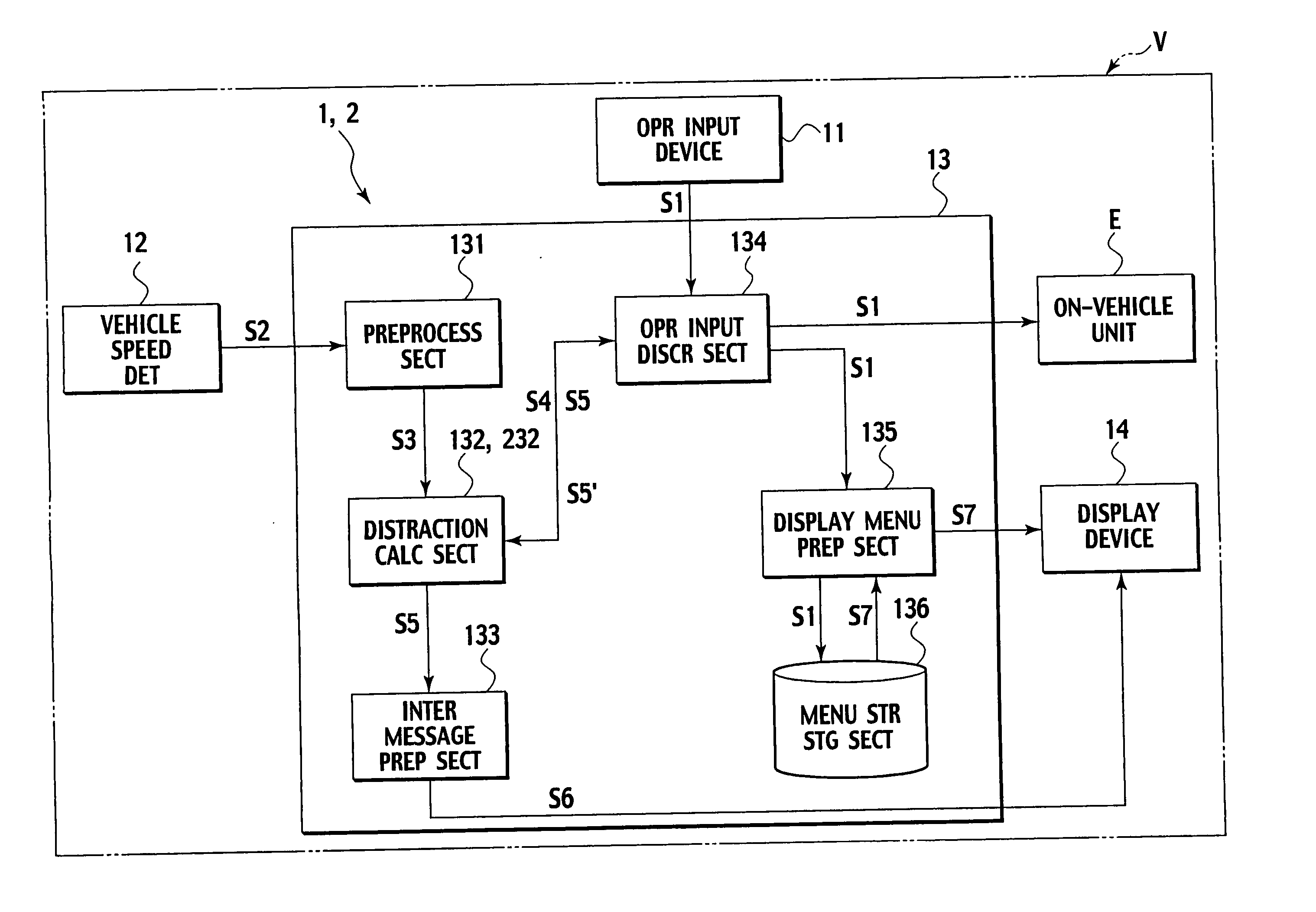
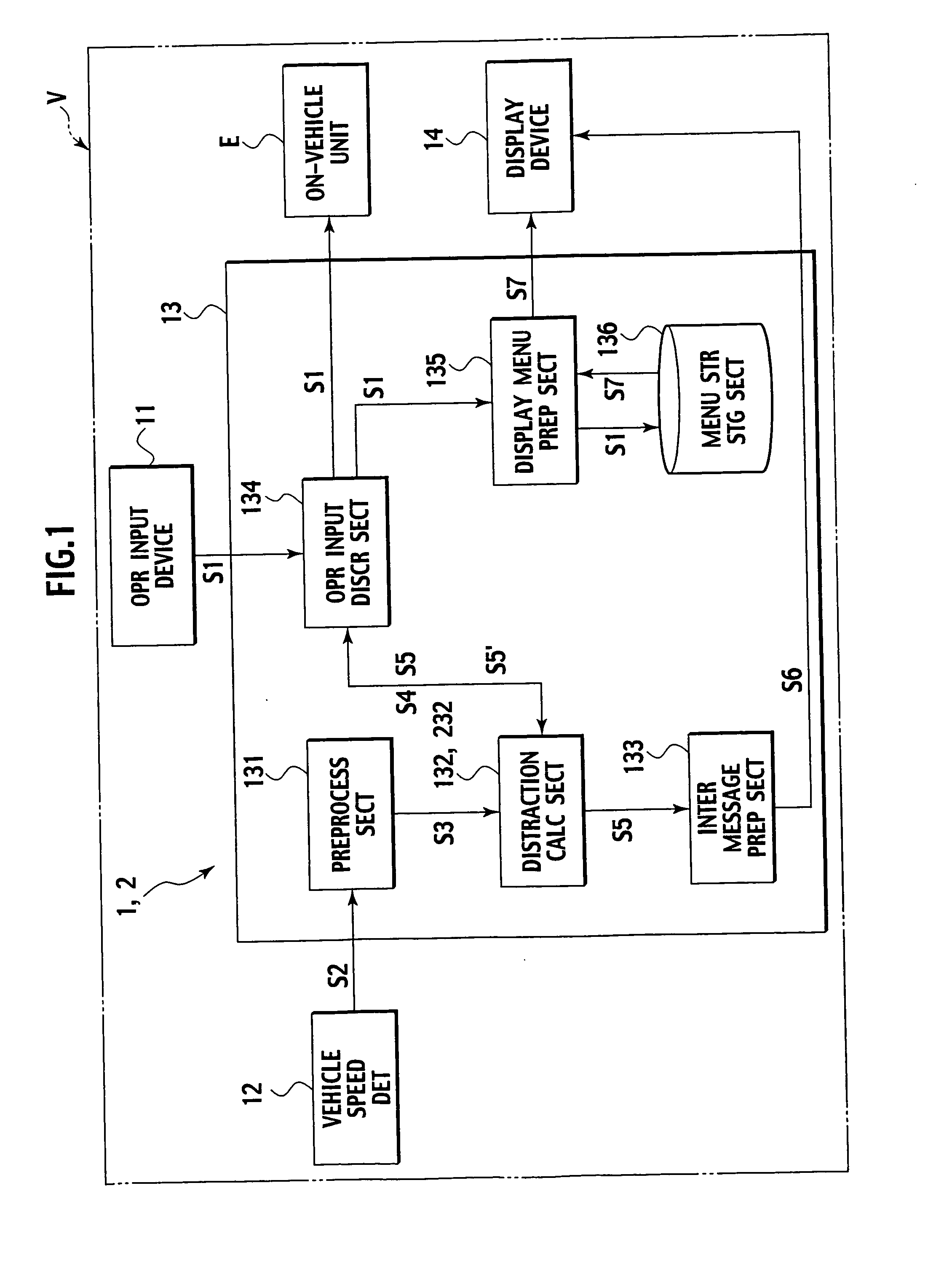
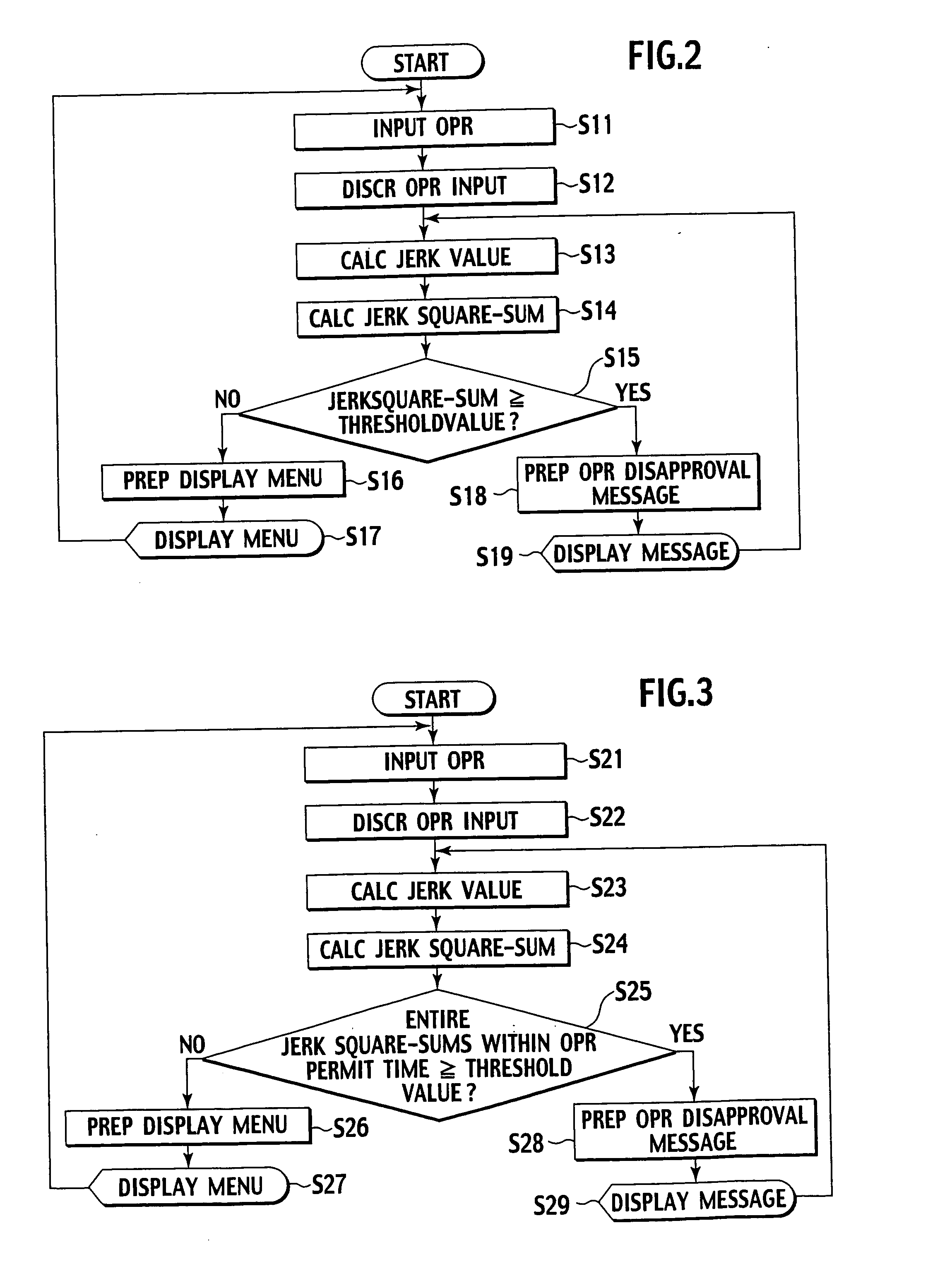
[0047] Hereunder, referring to FIGS. 1 and 2, the driving status detection device is described below in detail.

[0048]FIG. 1 is a block diagram showing an overall structure of the driving status detection device of the presently filed embodiment, and FIG. 2 is a flowchart showing a basic sequence of operations of the driving status detection device of the presently filed embodiment.

[0049] As shown in FIG. 1, the driving s...

second embodiment

[0088] Next, a driving status detection device and its related method of a second embodiment according to the present invention are described in detail with reference to FIGS. 1 and 3.

[0089]FIG. 3 is a flowchart illustrating a basic sequence of operations of the driving status detection device of the presently filed embodiment.

[0090] Although the driving status detection device 2 of the presently filed embodiment is described with respect to FIGS. 1 and 3 for the sake of convenience, the driving status detection device 2 mainly differs from that of the first embodiment in that a difference exists in a content of operations in a distraction calculating section 232. Hereunder, with attention focused on such a difference, the same component parts bear like reference numerals and description is suitably omitted or description is made in a simplified form.

[0091] As shown in FIG. 1 as a matter of convenience, the distraction calculating section 232 of the driving status detection devic...

third embodiment

[0103] Next, a driving status detection device and its related method of a third embodiment according to the present invention are described in detail with reference to FIGS. 4 to 6.

[0104] Although the driving status detection device 3 of the presently filed embodiment mainly differs from that of the second embodiment in respect of a difference in content of operations of a distraction calculating section 332. Hereunder, with attention focused on such a difference, the same component parts bear like reference numerals and description is suitably omitted or description is made in a simplified form.

[0105]FIG. 4 is a block diagram illustrating the structure of the driving status detection device 3 of the presently filed embodiment; FIG. 5 is a flowchart illustrating a basic sequence of operations of the driving status detection device of the presently filed embodiment; and FIG. 6 is a flowchart illustrating operations continuing from those of FIG. 5.

[0106] As shown in FIG. 4, the ve...


PUM


Abstract

In a driving status detection device and method for detecting a characteristic driving status during a drive of a vehicle, a vehicle speed is detected, a differentiated value of second order of the vehicle speed within a given time interval is calculated and a risk occurrence scene, which is a driving status at a high risk for a driver, is detected based on the differentiated value of second order of the vehicle speed.

Description

BACKGROUND OF THE INVENTION [0001] The present invention relates to a driving status detection device and a related method and, more particularly, to a driving status detection device and its related method that detects a characteristic driving status of a vehicle during a drive of a vehicle. [0002] Recently, proposals have heretofore been made to provide an operation data management system by which behavior of a moving object, such as vehicles and railroad trains, are managed. Such a system has a structure wherein measured data, related to behavior of the moving object, is registered and measured data after registration is analyzed for acquiring a vehicle behavior. [0003] Japanese Patent application Laid-Open Publication No. 2000-185676 discloses a device wherein high-risk behavior of a vehicle is detected to analyze a driving tendency for each driver. In particular, a structure is disclosed wherein comparison is made between a conditioning pattern, under which vehicle behavior is ...

Claims


Application Information

Patent Timeline
IPC IPC(8): B60K28/06G01P3/00G06F17/00
CPCB60W40/08B60W2540/22B60W50/16B60W2540/221
Inventor TAKAHASHI, TOSHIAKIINOUE, HIROFUMISEGUCHI, HIDENORI
Owner NISSAN MOTOR CO LTD
Learn More