
Digital high-resolution controller

a controller and high-resolution technology, applied in the field of electronic positioners, can solve the problems of reducing large coasting, requiring long periods of time, and delivering energy quantities more quickly (but with less computational precision), and achieve the effects of high efficiency, dramatic increase of resolution, and low cos

Active Publication Date: 2005-07-21
PEAKTRONICS
View PDF4 Cites 23 Cited by
  • Summary
  • Abstract
  • Description
  • Claims
  • Application Information

AI Technical Summary

Benefits of technology

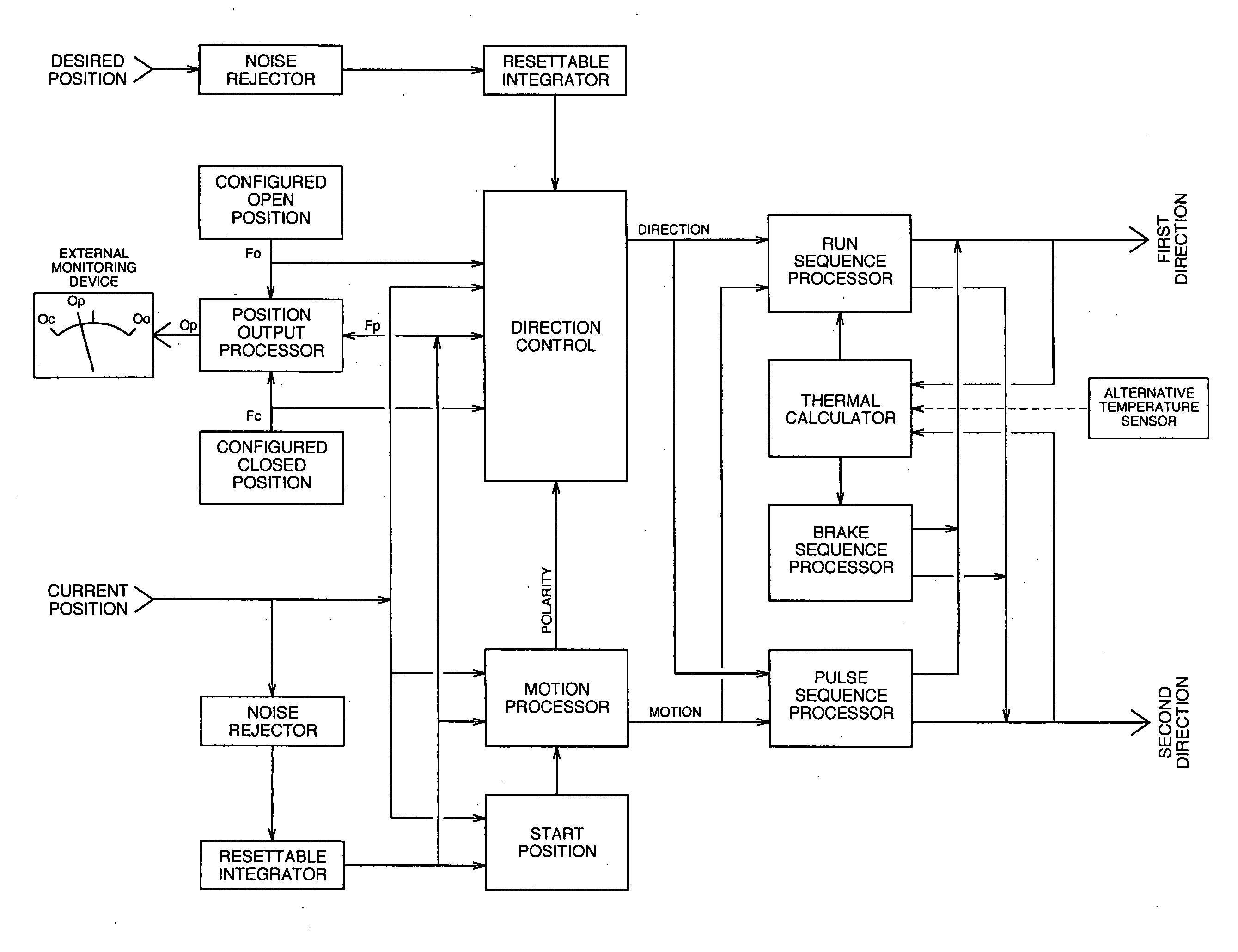
[0032] The present invention provides a low cost and yet highly effective solution for providing dramatically increased resolution. The controller employs a motor control algorithm that is capable of moving the motor to a desired motor position regardless of deadband or backlash. Unlike conventional control algorithms that adjust motor position (shaft position) based on measured position, the present algorithm establishes motor position based on observing motor motion. Energy is supplied in discrete quantities based on the motion produced by previous supplied energy quantities, and not merely based on the current static position of the motor shaft. Thus, the control algorithm is able to adapt to actual kinematic conditions. If the motor is controlling a valve that regulates a non-homogeneous viscous liquid, for example, the ability of the motor to open and close the valve may depend on the current viscosity of the liquid. The control algorithm can sense this condition and adapt accordingly.
[0034] In one preferred embodiment, the time interval between supplying of the first and second quantities of energy is controlled. When the current motor position is far from the desired position, quantities of energy are delivered at a first rate (delivered at spaced intervals according to a first period). When the current motor position gets closer to the desired position, quantities of energy are delivered at a second rate, preferably slower than the first rate. In this way, when the motor position is far from the desired position, energy quantities are delivered more rapidly (but with less computational precision). As the motor gets closer to the desired position, energy quantities are delivered more slowly. This allows time for the fractional inertial motion to be dissipated before delivering the next quantity of energy.
[0035] In another preferred embodiment, an electronic braking mechanism is invoked. Electronic braking reduces large coasting, which also requires long periods of time, after full power is applied to the motor. While not required in all applications, the electronic braking mechanism provides a means for attaining resolution accuracy in timely manner.
[0037] Among the many benefits of the new approach, motor overheating due to excessive cycling and due to stall conditions is reduced. Incorrect or unstable operation due to rapid or erroneous signal changes or due to electrical noise or environmental conditions is also eliminated. Installation and setup of the positioner is also greatly simplified because the new approach makes possible: automatic polarity detection to eliminate incorrect operation due to wiring; elimination of calibration steps and procedures; elimination of instrumentation used for setup; and convenient three button digital control to configure all setup parameters.

Problems solved by technology

In this way, when the motor position is far from the desired position, energy quantities are delivered more rapidly (but with less computational precision).
Electronic braking reduces large coasting, which also requires long periods of time, after full power is applied to the motor.

Method used


Image

  • Digital high-resolution controller
  • Digital high-resolution controller
  • Digital high-resolution controller

Examples


Embodiment Construction

[0056] The following description of the preferred embodiment(s) is merely exemplary in nature and is in no way intended to limit the invention, its application, or uses.

[0057] Kinematic Control of Electronic Positioner

[0058] The digital high-resolution controller effects kinematic control of the electronic positioner and its associated actuator. High accuracy is achieved through a kinematic control algorithm that measures and adapts to actual observed motion of the actuator and mechanical systems coupled to the actuator. A detailed discussion of the new kinematic control system will now be presented.

[0059] Control Algorithm Overview

[0060] Referring to FIG. 10, an overview of the control algorithm will first be presented. FIG. 10 illustrates the control algorithm as a collection of interconnected functional processes. These processes may be carried out by a suitably programmed microprocessor (shown in the circuit diagram of FIG. 11 discussed below.) According to the presently pre...


PUM


Abstract

Kinematic control of an electronic positioner and its associated actuator is effected through a control algorithm that delivers energy to the actuator based on observed motion produced by a previous delivery of energy. The algorithm achieves control based on a desired or user-specified resolution. Electronic braking between energy delivery intervals improves the speed at which the desired position is achieved. Temperature of the force producing mechanism is determined, as by monitoring energy consumed, and used to control how power is delivered to the actuator.

Description

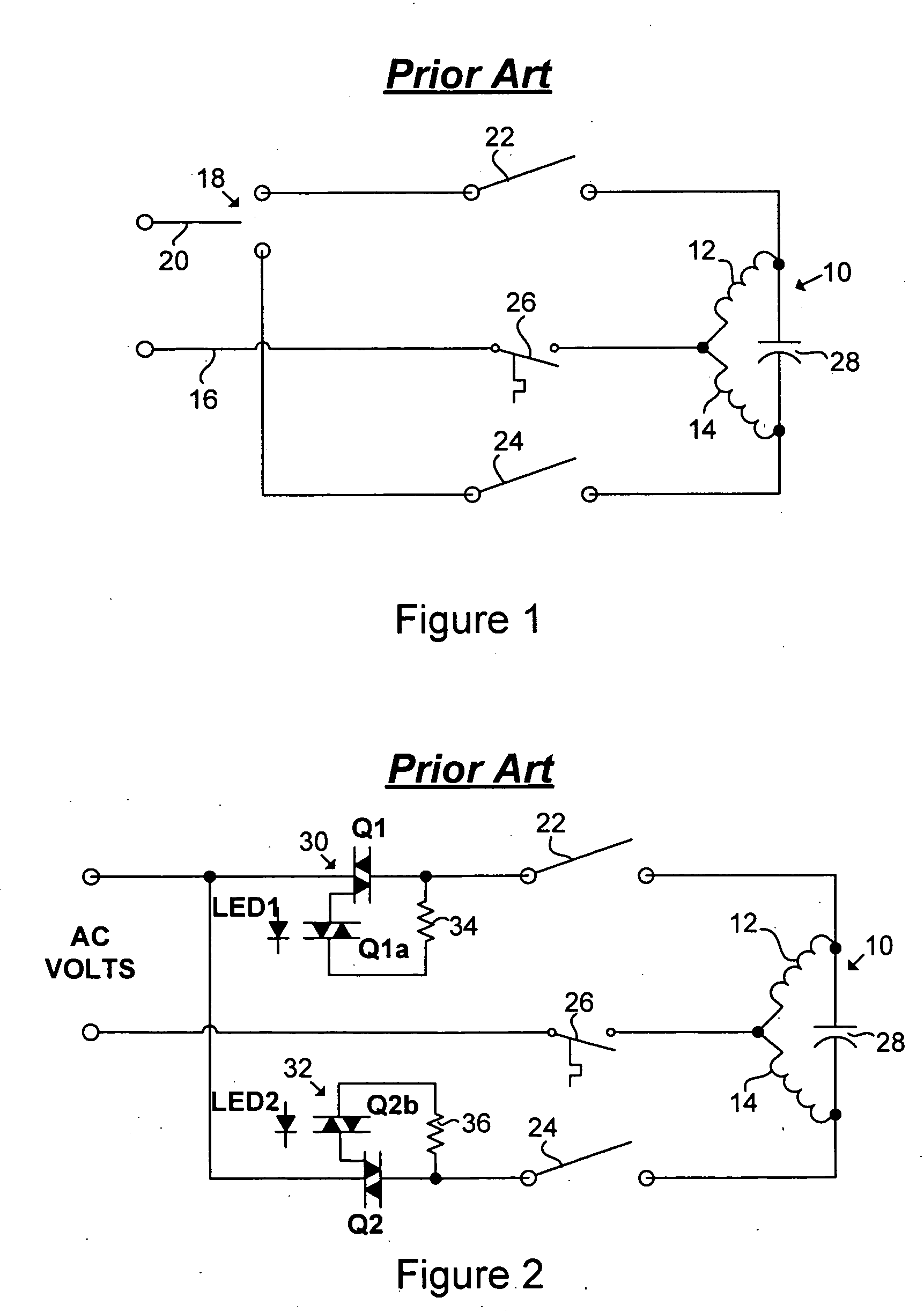
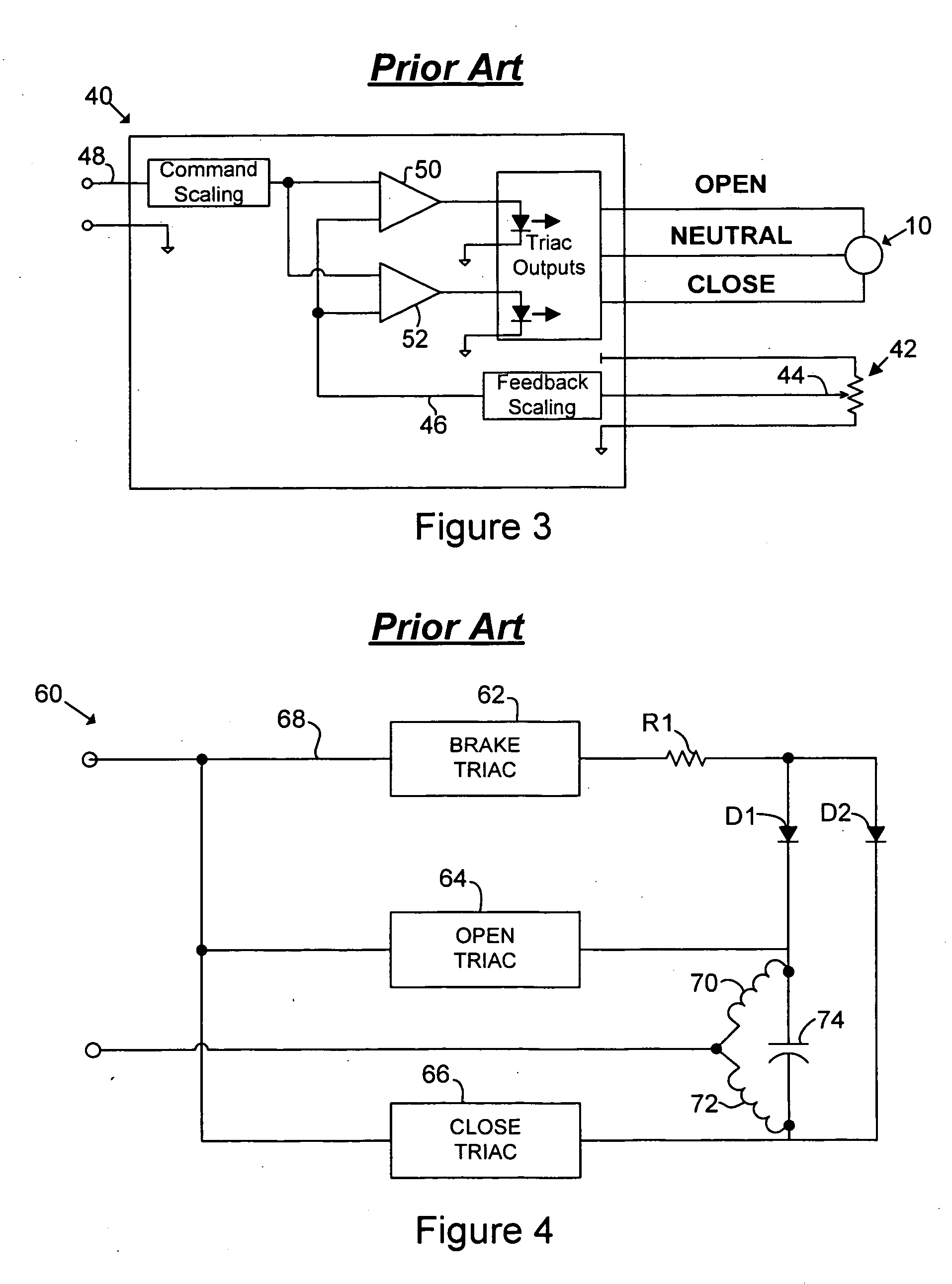
CROSS-REFERENCE TO RELATED APPLICATIONS [0001] This application claims the benefit of U.S. Provisional Application No. 60 / 538,106, filed on Jan. 21, 2004. The disclosure of the above application is incorporated herein by reference.FIELD OF THE INVENTION [0002] The present invention relates to an electronic positioner, and more particularly to kinematic control of an electronic positioner and its associated actuator. BACKGROUND OF THE INVENTION [0003] An electronic microprocessor-based unit may be used to control an actuator used in a variety of automated valve applications. Such a unit is commonly referred to as an electronic positioner, or simply a “positioner,” or as a servo card, or simply a “servo.” An AC actuator is an electromechanical device that uses a motor, such as an AC split phase motor or even a three-phase motor, to rotate an output shaft that can be mechanically coupled to a valve, thus allowing the actuator to open and close the valve. A DC actuator uses a DC motor. ...

Claims


Application Information

Patent Timeline
IPC IPC(8): G05B19/29H02P3/00
CPCG05B19/291G05B2219/42115Y10S388/934H02P3/18H02P1/44H02P3/00H02P6/16
Inventor MUELLER, PETER W.LEASON, JACK M.
Owner PEAKTRONICS
Learn More