Fuel supply apparatus
a technology of fuel supply and apparatus, which is applied in the direction of liquid fuel feeders, machines/engines, and feed systems, etc., can solve the problems of low degree of freedom of spring design such as spring constant, inferior dimension accuracy of fuel tanks, and easy deformation of fuel pumps, etc., to achieve simple construction
- Summary
- Abstract
- Description
- Claims
- Application Information
AI Technical Summary
Benefits of technology
Problems solved by technology
Method used
Image
Examples
embodiment 1
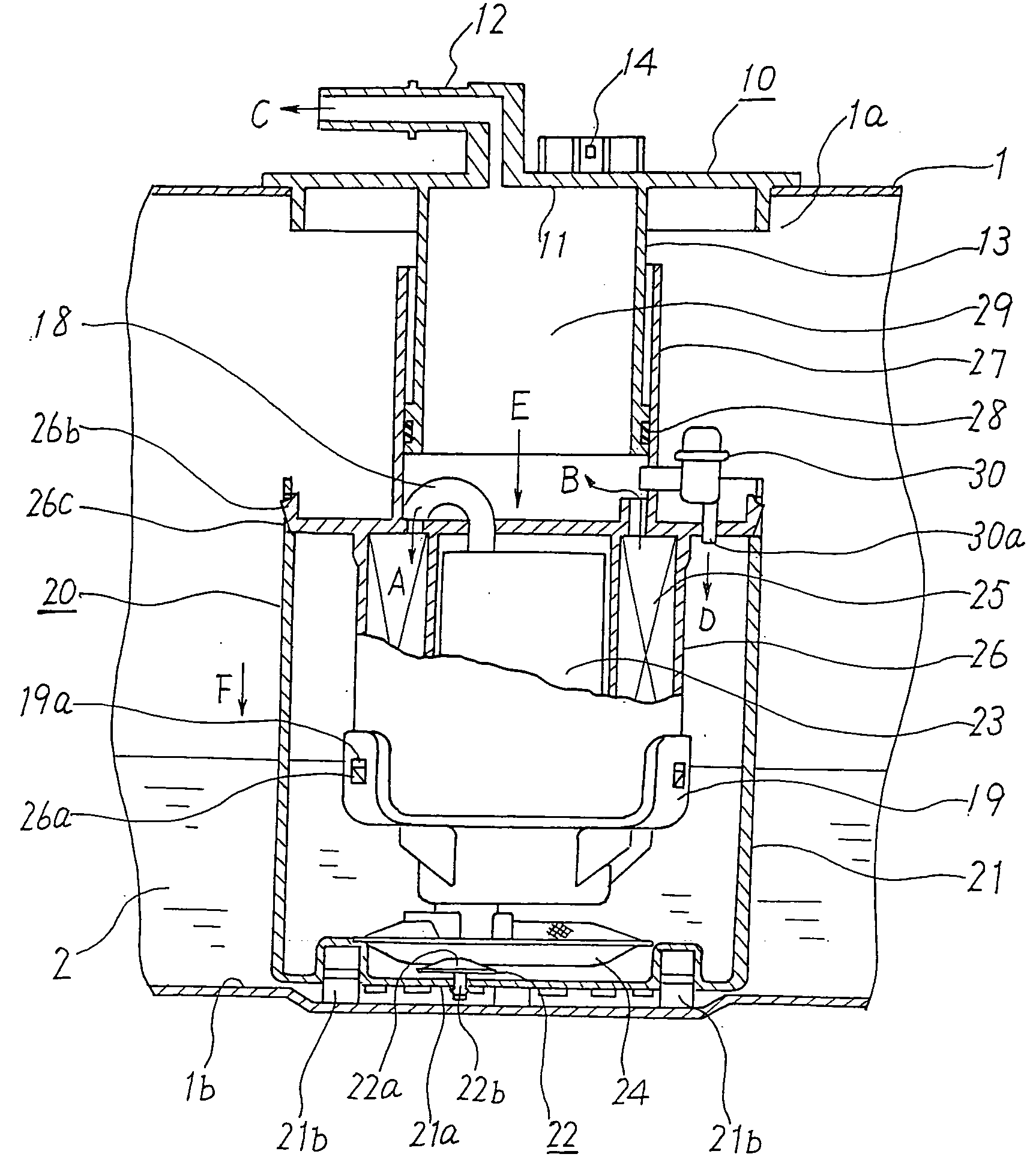
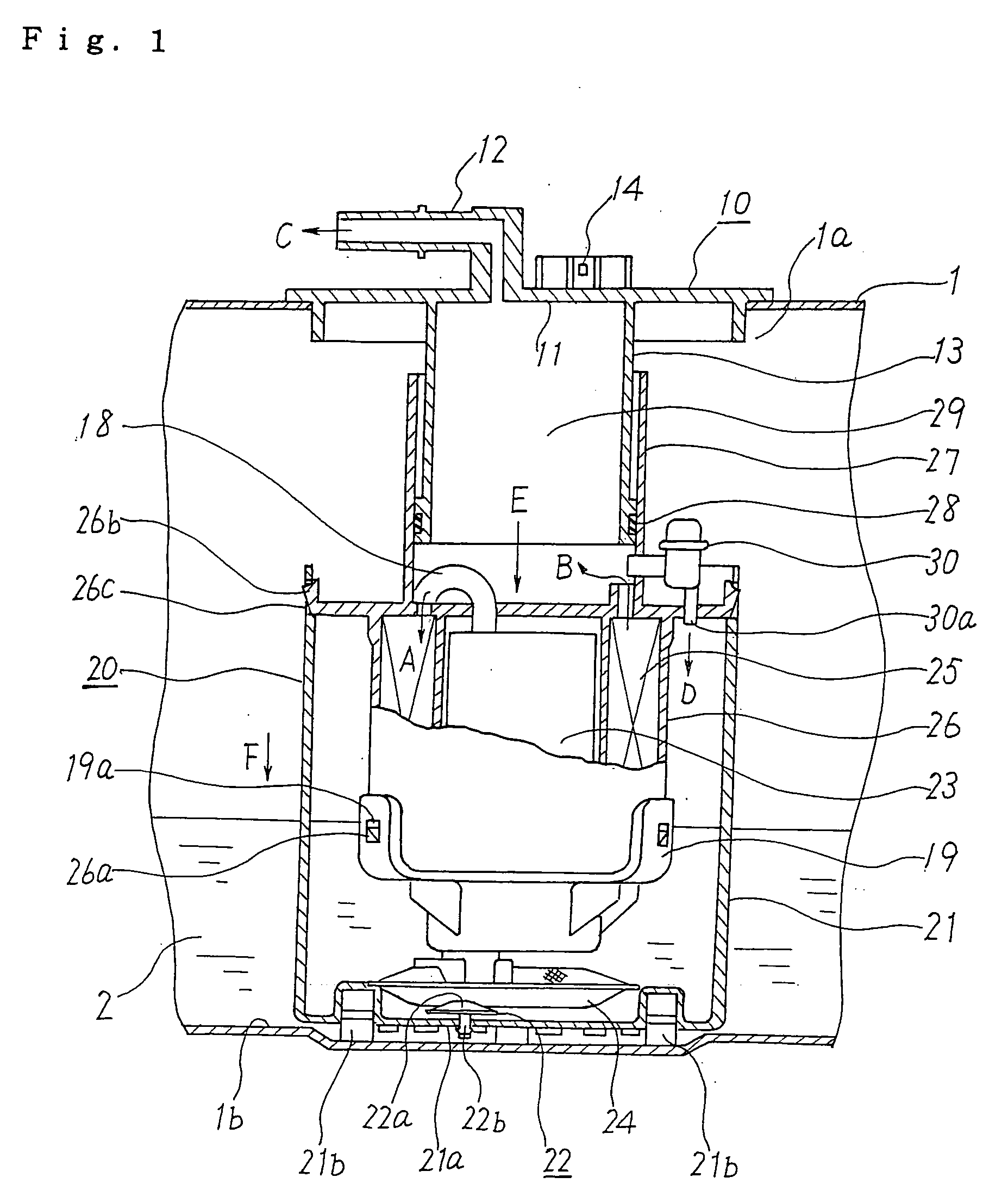
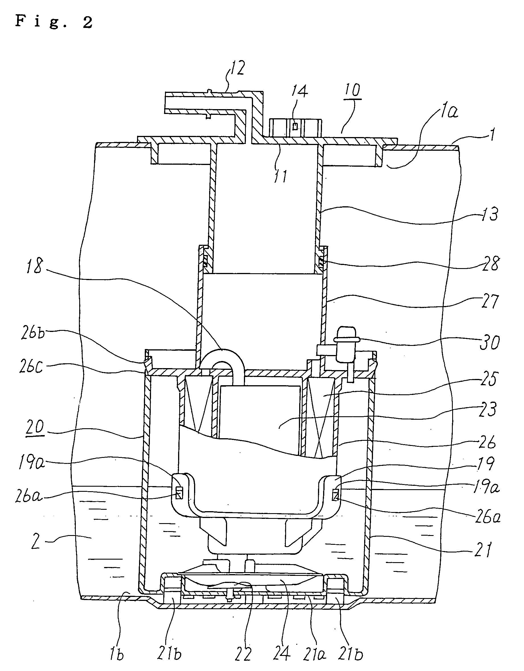
[0031]FIG. 1 is a longitudinal cross-sectional view of a fuel supply apparatus according to Embodiment 1 of the invention, and shows the case where the position of the bottom side of a fuel tank is shallow, while FIG. 2 is a longitudinal cross-sectional view of the fuel supply apparatus according to Embodiment 1 of the invention, and shows the case where the position of the bottom side of the fuel tank is deep. FIG. 3 is a bottom view of the fuel supply apparatus shown in FIG. 1, FIG. 4 is an enlarged view of the essential portion of FIG. 3, and FIG. 5 is an enlarged view of an air-tight member shown in FIG. 1.
[0032] Referring to FIG. 1, the fuel supply apparatus includes a fuel tank lid unit 10 which is externally fitted in a tank opening 1a formed in a fuel tank 1, and a fuel pump body 20 which is disposed in the fuel tank 1 so that the bottom side of the fuel pump body 20 can come into abutment with a tank bottom 1b and which stably discharges and supplies fuel 2 from the fuel t...
embodiment 2
[0049]FIG. 6 is a longitudinal cross-sectional view of a fuel supply apparatus according to Embodiment 2 of the invention, and shows the case where the position of the bottom side of the fuel tank is shallow, while FIG. 7 is a longitudinal cross-sectional view of the fuel supply apparatus according to Embodiment 2 of the invention, and shows the case where the position of the bottom side of the fuel tank is deep. In FIGS. 6 and 7, the same constituent elements and portions as those used in Embodiment 1 are denoted by the same reference numerals. The following description focuses on points different from Embodiment 1. The discharge port of the fuel filter 25 and the fuel discharge passage portion 12 are arranged to directly communicate with each other by means of a connecting member 31 which is formed in a coiled shape, whereby after the fuel discharged from the fuel filter 25 has flown into the connecting member 31 (in the direction of an arrow H), the fuel is transferred from the f...
embodiment 3
[0052] A fuel supply apparatus according to Embodiment 3 is a modification of Embodiment 2, and FIG. 8 is a longitudinal cross-sectional view of the fuel supply apparatus, and shows the case where the position of the bottom side of the fuel tank is shallow, while FIG. 9 is a longitudinal cross-sectional view of the fuel supply apparatus, and shows the case where the position of the bottom side of the fuel tank is deep. In FIGS. 8 and 9, the same constituent elements and portions as those used in Embodiment 2 are denoted by the same reference numerals. The following description focuses on points different from Embodiment 2. The tank bottom 1b of the fuel tank 1 is formed to have a cavity portion 1c, and the bottom of the fuel pump body 20 is fitted in the cavity portion 1c so that the cavity portion 1c serves as a guide portion for guiding the vertical movement of the fuel pump body 20. In this construction, the guide tube portion 13 and the sliding tube portion 27 are omitted. It is...
PUM
 Abstract
Description
Claims
Application Information
 - R&D
- Intellectual Property
- Life Sciences
- Materials
- Tech Scout
- Unparalleled Data Quality
- Higher Quality Content
- 60% Fewer Hallucinations
Browse by: Latest US Patents, China's latest patents, Technical Efficacy Thesaurus, Application Domain, Technology Topic, Popular Technical Reports.
© 2025 PatSnap. All rights reserved.Legal|Privacy policy|Modern Slavery Act Transparency Statement|Sitemap|About US| Contact US: help@patsnap.com


