
Medical material handling systems

a technology for handling systems and medical materials, applied in the direction of packaging foodstuffs, instruments, packaged goods, etc., can solve the problems of horrifying heart lung transplant surgery failur

Inactive Publication Date: 2005-07-14
VASOGEN IRELAND LTD
View PDF45 Cites 81 Cited by
  • Summary
  • Abstract
  • Description
  • Claims
  • Application Information

AI Technical Summary

Benefits of technology

"The present invention provides a system for collecting, treating, and delivering an autologous blood sample. The system includes two syringes, a blood sample treatment chamber, and a blood sample delivery unit. The first syringe has a sample transfer portion with a dedicated fluid coupling for drawing the untreated blood sample from the patient and dispensing it to the treatment chamber. The second syringe has a dedicated fluid coupling for dispensing the treated blood sample from the chamber. The system also includes identification means for identifying the patient and verification means for confirming a match between the untreated and treated blood samples. The system can be used in a blood sample treatment process where the untreated blood sample is collected, treated, and then delivered to the patient. The system provides a convenient and efficient way to collect, treat, and deliver autologous blood samples for medical purposes."

Problems solved by technology

A recent heart lung transplant surgery went horribly wrong because of a relatively minor oversight—a mismatch in the blood type of the donor and recipient patients.

Method used


Image

  • Medical material handling systems
  • Medical material handling systems
  • Medical material handling systems

Examples


Embodiment Construction

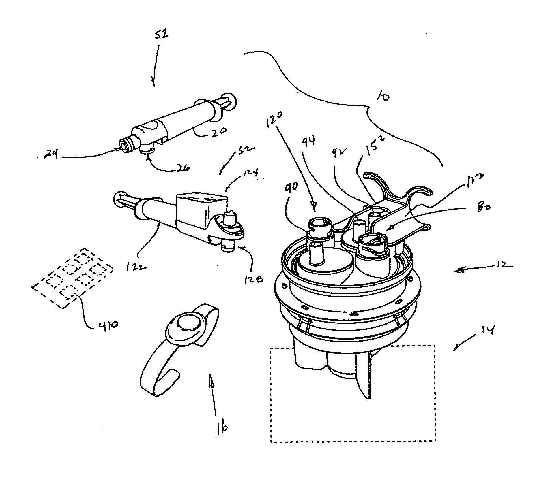
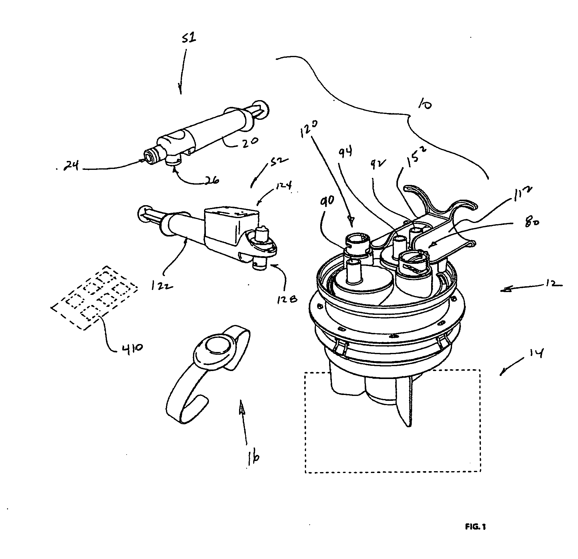
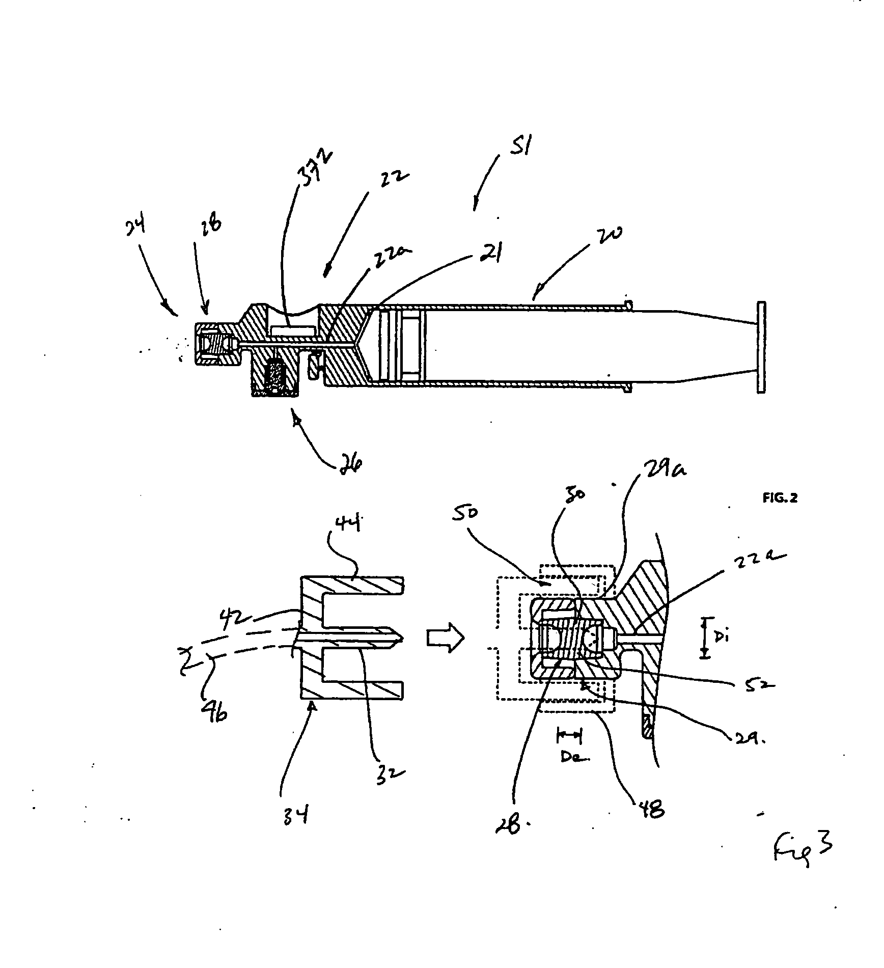
[0085] Referring to the figures, particularly FIG. 1, there is provided a system 10 for the collection, treatment and delivery of an autologous blood sample. The system 10 has a number of components which are used at different stages during the handling of the blood sample. As will be described, the system makes use of a first blood sample collection syringe S1 which used to collect an untreated blood sample from an originating patient. Following blood sample collection, the first syringe S1 is connected to a blood treatment chamber 12 which is then delivered to a blood treatment unit shown schematically at 14 in which the blood sample is subjected to one or more stressors as, for example, described in PCT application serial number PCT / CAOO / 0 1078 filed Sep. 15, 2000 entitled APPARATUS AND PROCESS FOR CONDITIONING MAMMALIAN BLOOD (the entire contents of which are incorporated herein by reference).

[0086] Following treatment, the treated blood sample is delivered to a second syringe ...


PUM


Abstract

Disclosed herein is a system for the collection, treatment and delivery of an autologous blood sample, comprising a first syringe having a first body portion. A first sample transfer portion has a first syringe inlet for drawing an untreated blood sample from a patient and a first syringe outlet for dispensing the untreated blood sample. A blood sample treatment chamber having a chamber inlet, the first syringe outlet being operable to establish a dedicated first fluid coupling with the chamber inlet to dispense the untreated blood sample to the blood sample treatment chamber. The blood sample treatment chamber having a chamber outlet for dispensing a treated blood sample following treatment. The second syringe has a second body portion and a second sample transfer portion, the second sample transfer portion having a passage with a first access location which is operable to form a dedicated second fluid coupling with the chamber outlet. The second body portion has a second syringe outlet, the passage having a second access location for fluid communication with the second syringe outlet, releasable lock means for forming a locked third fluid coupling between the second access location and the second syringe outlet. The lock means is operable in response to a release signal to release the third fluid coupling, the second syringe outlet being operable when released from the third fluid coupling to form a fourth fluid coupling with a blood sample delivery unit.

Description

[0001] This application claims priority under 35 U.S.C. § 119(e) with respect to U.S. provisional application No. 60 / 523,701 filed on Nov. 21, 2003.REFERENCE TO CO-PENDING APPLICATIONS [0002] The entire subject matter of U.S. Provisional application Ser. No. 60 / 421,781 filed Oct. 29, 2002 and entitled DEVICE AND METHOD FOR CONTROLLED EXPRESSION OF GASES FROM MEDICAL FLUIDS DELIVERY SYSTEMS is incorporated by reference. [0003] The entire subject matter of U.S. Provisional application Ser. No. 60 / 428,942 filed Nov. 26, 2002 and entitled BLOOD TREATMENT CONTROL SYSTEM is incorporated by reference. [0004] The entire subject matter of U.S. Provisional application Ser. No. 60 / 464,659 filed Apr. 23, 2003 and entitled DISPENSING SYSTEMS is incorporated by reference. [0005] The entire subject matter of U.S. Provisional application Ser. No. 60 / 482,725 filed Jun. 27, 2003 and entitled MEDICAL TREATMENT CONTROL SYSTEM is incorporated by reference. [0006] The entire subject matter of PCT Patent ...

Claims


Application Information

Patent Timeline
Patent Type & Authority Applications(United States)
IPC IPC(8): A61J1/00A61J1/14A61M1/02A61M5/178A61M5/19A61M5/31A61M39/00G06F19/00
CPCA61J1/1437A61M5/178A61M5/19A61M2205/6045A61M2005/3128A61M2205/6018A61M39/00A61B5/1405A61M1/02
Inventor LIM, BERNARD C.B.WORONA, TARASKANBERGS, DAVIS A.R.COSTA, MARK PAULZHAO, ROY T.KLEIN, GABRIELEMULLER, KATHLEENMATSUURA, DAVID G.SIMPSONGILLESPIE, WALTER DEANMITCHELL, JOHN NORRISCHEN, HAO
Owner VASOGEN IRELAND LTD
Learn More