
Method of separating biocomponents contained in a liquid, a separating system and a separating unit

a biocomponent and liquid separation technology, applied in the direction of liquid/fluent solid measurement, fluid pressure measurement, peptides, etc., can solve the problems of time and labor-intensive traditional gel electrophoresis techniques, inability to resolve and inability to solve all proteins present in single ief gel. , to achieve the effect of reducing the bonding of non-specific molecules or components

Inactive Publication Date: 2005-07-14
SCHMIDT HENRIK +5
View PDF26 Cites 5 Cited by
  • Summary
  • Abstract
  • Description
  • Claims
  • Application Information

AI Technical Summary

Benefits of technology

[0019] Thus in some of the embodiments, non-denatured proteins can be separated, because the biomolecules are adsorbed to (and are mobile on) the separation layer. This provides the further advantage that separated proteins or other biocomponents can be tested directly for biological activity without the need for an isolation and optional re-folding step.
[0130] In one embodiment of the invention, substrates that is absorb large amounts of liquid i.e. such as 100% of the weight of the substrate or more due to migration into and optionally chemical binding of the liquid in the material are avoided, because this bonding of water may disturb the separation, and furthermore the liquid may be drained from the sample comprising the biocomponents to be separated.

Problems solved by technology

Traditional gel electrophoresis techniques are however time and labour consuming and may involve limitations with respect to resolution.
However, a single IEF gel cannot resolve all of the proteins present in a single cell type since there are typically more than 20,000 different proteins in a cell.

Method used

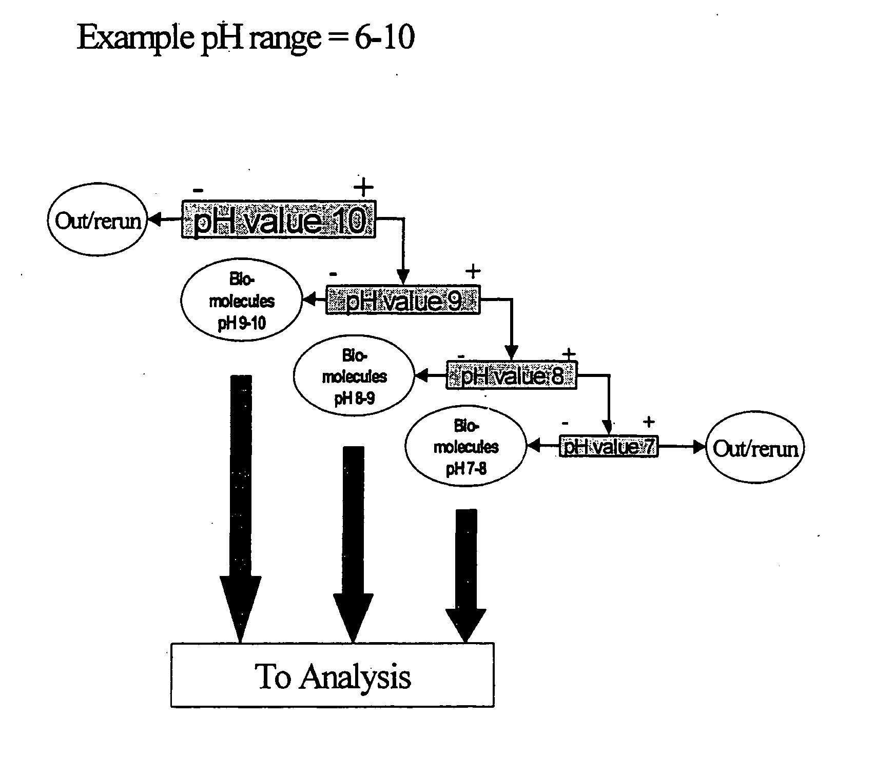
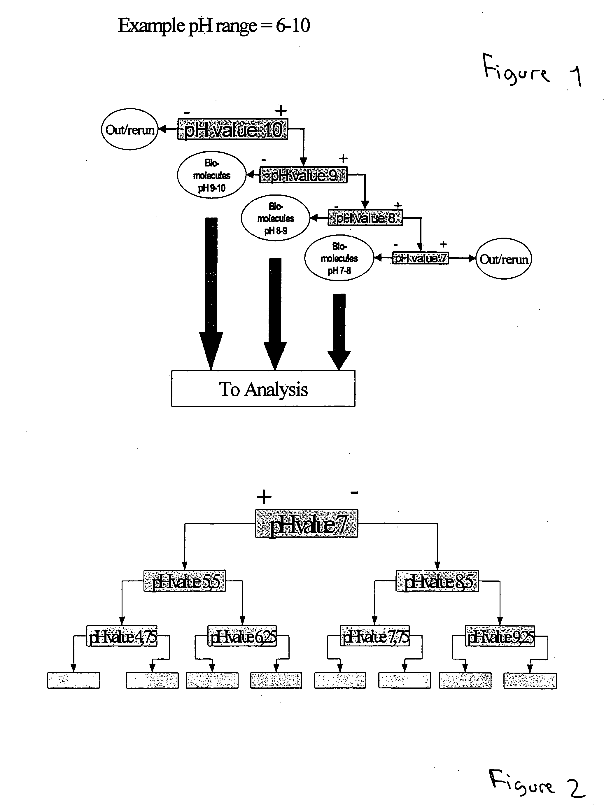

Image

  • Method of separating biocomponents contained in a liquid, a separating system and a separating unit
  • Method of separating biocomponents contained in a liquid, a separating system and a separating unit
  • Method of separating biocomponents contained in a liquid, a separating system and a separating unit

Examples


example 1

Manufacturing a Separating Path with a pH-Gradient for Separation of Proteins

[0210] 1 g Dodecylamine in 100 ml acetone is mixed with 1% UV curing agent (loctite 3201).

[0211] 1 g of Maleic acid in 100 ml acetone is mixed with 1% UV curing agent (loctite 3201).

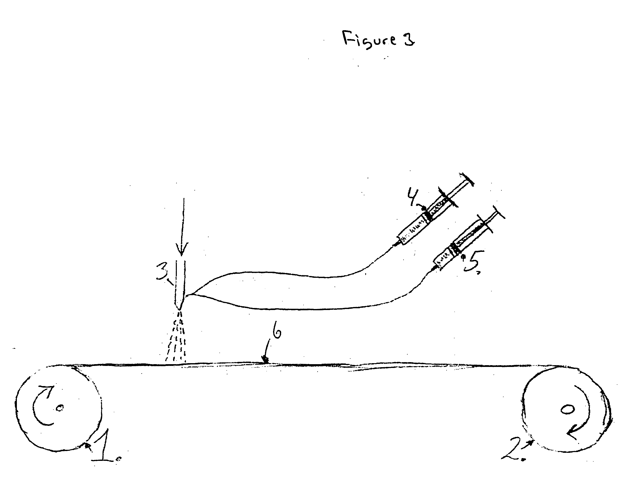
[0212] The solutions are placed in the dosing apparatus (a Hawad syringe pump,) that can be controlled. The dosing from each of the syringes can be varied with time. The two separate flows of material are merged together in a small static mixture, then dosed into the substrate though a needle.

[0213] The 30 mm wide VK1100 substrate for the pH-gradient is then wetted with a mixture of acid, base and UV adhesive soluted in the solvent as the substrate at a constant speed passes the premixed mixture flowing out of the needle. The substrate with the solution added then passes an evaporation chamber for evaporation of the acetone and then an UV source for curing. The substrate is re-spooled on a reel pulled by a 24 V DC motor.

[02...

example 2

Manufacturing a Separating Path with a pH-Gradient for Separation of Proteins

[0217] 1 g Hisdidine (amino acid) base in 100 ml water is mixed with 1% UV curing agent (loctite 3201).

[0218] 1 g Lysine (amino acid) acid in 100 ml water is mixed with 1% UV curing agent (loctite 3201).

[0219] The solutions are placed in the dosing apparatus (a Hawad syringe pump) that can be controlled. The dosing from each of the syringes can be varied with time. The two separate flows of material are merged together in a small static mixture, then dosed into the substrate though a needle.

[0220] The 30 mm wide VK1100 substrate for the pH-gradient is then wetted with a mixture of premixed amino acid and amino acid base and adhesive soluted in the solvent as the substrate at a constant speed flows out of the needle. The substrate with the solution added then passes an evaporation chamber causing the water to evaporate and then an UV source for curing. The substrate is re-spooled on a reel pulled by a 24...

example 3

Manufacturing a Separating Path with a pH-Gradient for Separation of Proteins

[0223] 0.1 mol Maleic acid in 100 ml acetone is mixed with 0.01% UV curing agent (Irgacure 369 from Cibasc).

[0224] 0.1 mol Allylamine in 100 ml acetone is mixed with 0.01% UV curing agent (Irgacure 369 from Cibasc).

[0225] The solutions are placed in the dosing apparatus (a Haward syringe pump) that can be controlled. The dosing from each of the syringes can be varied with time. The two separate flows of material are merged together in a small static mixture, then dosed into the substrate though a needle.

[0226] In order to obtain a good adhesion of the acid and base to the substrate, it is pre-treated with e.g. hexene in as plasma process.

[0227] The 30 mm wide VK1100 substrate for the pH-gradient is then wetted with a mixture of acids, bases and adhesives soluted in the acetone as the substrate at a constant speed passes the premixed acid and base flowing out of the needle. The substrate with the soluti...


PUM

PropertyMeasurementUnit
Fractionaaaaaaaaaa
Fractionaaaaaaaaaa
Electric field strengthaaaaaaaaaa

Abstract

The invention relates to a method of separating at least two biocomponents contained in a liquid including having different pI values. The method comprising the steps of: i. providing a first separating path with at least one separating layer comprising one or more pH active components with pH active groups, ii. applying the liquid with the biocomponents to the separating coating, iii: applying a voltage over the separating path, iv. allowing at least some of the biocomponents to travel towards one of the electrodes to one or more collection stations, v. collecting the once separated biocomponents from at least one collection station. The invention also relates to a separating system for use in the method. The separation system comprises a set of separating paths, the separating system comprising 2 or more separating paths that differ from each other with respect to the pH value of the separating coating.

Description

FIELD OF THE INVENTION [0001] The present invention relates to a method of separating biocomponents contained in a liquid, such as biomolecules including proteins and nucleic acids. The invention also includes a separating system and a separating unit, which can be used in the method. BACKGROUND OF THE INVENTION [0002] Separation of proteins from a complex mixture has traditionally been performed by utilising chromatographic techniques or gel electrophoresis techniques. Traditional gel electrophoresis techniques are however time and labour consuming and may involve limitations with respect to resolution. [0003] pH gradients in gels have e.g. been provided for polyacrylamide matrices as described in WO 93 / 11174 and WO 97 / 16462. [0004] Since 1975, complex mixtures of proteins have generally been separated by means of two dimensional gel electrophoresis in which the physical separation of the proteins in the first dimension gel is based upon a separation according to the isoelectric po...

Claims


Application Information

Patent Timeline
IPC IPC(8): A61M1/00A61M1/02C07K1/28C07K14/195C07K14/415C07K14/47G01N27/447
CPCG01N27/44747G01N27/44795G01N27/44773
Inventor SCHMIDT, HENRIKPRYDS, STEFFENFALTUM, CARSTENFEY, STEPHEN J.LARSEN, PETER MOSERUBIN, ADAM
Owner SCHMIDT HENRIK
Learn More