
Loader/excavator-type heavy construction machine and method of controlling the operation of one such machine

Inactive Publication Date: 2005-07-14
VOLVO CONSTR EQUIP
View PDF4 Cites 10 Cited by
  • Summary
  • Abstract
  • Description
  • Claims
  • Application Information

AI Technical Summary

Benefits of technology

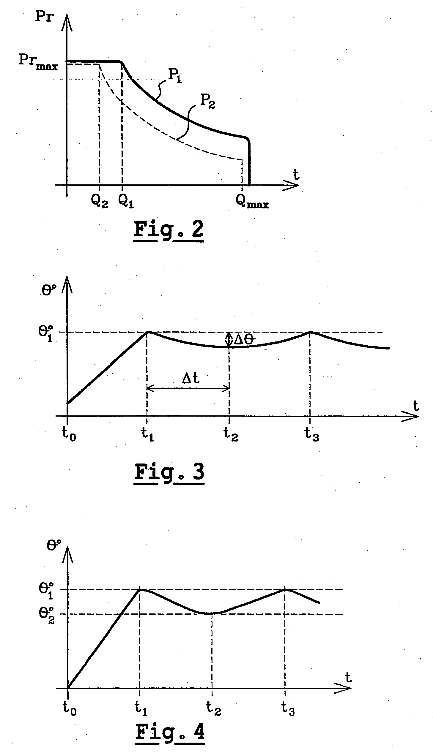
[0010] In other words, the invention involves limiting the power available for the hydraulic circuit by reducing the maximum power of the variable-delivery pump when the temperature exceeds a predetermined threshold, typically around 90° C. This switching takes place automatically without requiring the intervention of the driver. The shift to reduced power mode means that the losses due to friction within the hydraulic circuit are reduced and therefore normally lead to a drop in the oil temperature. Thus, the driver can continue to carry out the various operations while benefiting, however, from a lower rate of execution, but with the integrity of the hydraulic circuit being preserved.
[0014] Thus, in a first variant embodiment, the return to full power mode takes place when the temperature of the oil circuit has remained below the aforementioned trigger threshold for a predetermined time. In other words the reduction in the oil temperature is then estimated according to a time which depends on the parameters of the hydraulic circuit, specifically its volume, its geometry, etc., and also the intrinsic characteristics of the oil used, particularly its specific heat capacity. In practice, it is considered that if the temperature has remained below the predetermined threshold for a given time, of around seven minutes, that is sufficient to obtain a lowering of the temperature of around 15° C., with the result that it is then possible to allow operation at full power once more.

Problems solved by technology

The shift to reduced power mode means that the losses due to friction within the hydraulic circuit are reduced and therefore normally lead to a drop in the oil temperature.

Method used


Image

  • Loader/excavator-type heavy construction machine and method of controlling the operation of one such machine
  • Loader/excavator-type heavy construction machine and method of controlling the operation of one such machine
  • Loader/excavator-type heavy construction machine and method of controlling the operation of one such machine

Examples


Embodiment Construction

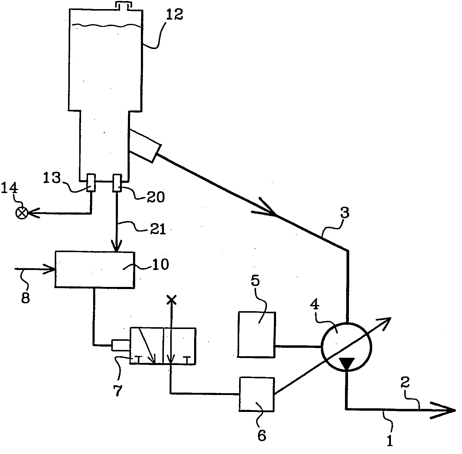
[0024] The hydraulic circuit (1) illustrated in FIG. 1 comprises various tubes (2) routed toward or originating from the various hydraulically operated elements, such as cylinders, hydraulic motors or other distributors, which do not have a direct bearing on the invention and will therefore not be described or represented in detail. This hydraulic circuit (1) comprises a variable-delivery pump (4) which is driven by the internal combustion engine (5) of the machine. The pump (4) is connected to the oil reservoir (12) by means of an intake line (3). The flow rate and pressured delivered by the pump (4) are regulated by a system (6) known per se, which will not be described in any more detail. This regulating device (6) particularly allows the pump (4) to operate in two separate modes, namely a full power mode and a reduced power mode, in which about two-thirds of the power is available with respect to the full power mode. The shift from one mode to the other is controlled by means of...


PUM


Abstract

The invention relates to a loader / excavator-type heavy-construction machine comprising a hydraulic system which powers one or more hydraulic actuators. The aforementioned hydraulic system is equipped with a variable-delivery pump which can operate in two different modes, namely full power mode for use as an excavator and reduced power mode for use as a loader. The invention is characterized in that it also comprises a temperature sensor which is used to determine the temperature of the oil in the hydraulic system and means of automatically switching the operation of the pump from full power mode to reduced power mode when the oil temperature exceeds a pre-determined threshold.

Description

TECHNICAL FIELD [0001] The invention relates to the field of heavy-construction machines. It is concerned more precisely with machines equipped with a hydraulic circuit and performing the combined functions of loader and excavator. It relates more specifically to special hydraulic circuit equipment intended to protect these circuits from the rises in temperature of the oil circulating therein. PRIOR ART [0002] Heavy-construction machines are generally equipped with a hydraulic circuit inside which oil circulates. This hydraulic circuit supplies the various cylinders of the operating equipment which move and are deployed during the various maneuvers of the machine. During operation, and particularly when the machine has a considerable work load, for example when carrying out excavations at “depth” for a long period of time, the temperature of the oil circulating in the hydraulic circuit rises. An excessive rise in this temperature causes deterioration not only of the oil but of vario...

Claims


Application Information

Patent Timeline
IPC IPC(8): F04B49/06
CPCF04B2205/11F04B2205/10F04B49/06
Inventor CHARLES, GEORGES
Owner VOLVO CONSTR EQUIP
Learn More