
Monitoring system for a mobile storage tank

a monitoring system and mobile storage technology, applied in the direction of wireless architecture, container discharge methods, instruments, etc., can solve the problems of mobile storage containers arriving at their destinations with a high percentage of product loss or empty, vaporization of liquefied gas, product loss, etc., to quickly detect accidental handling and limit power on board

Active Publication Date: 2005-04-21
PRAXAIR TECH INC
View PDF5 Cites 31 Cited by
  • Summary
  • Abstract
  • Description
  • Claims
  • Application Information

AI Technical Summary

Benefits of technology

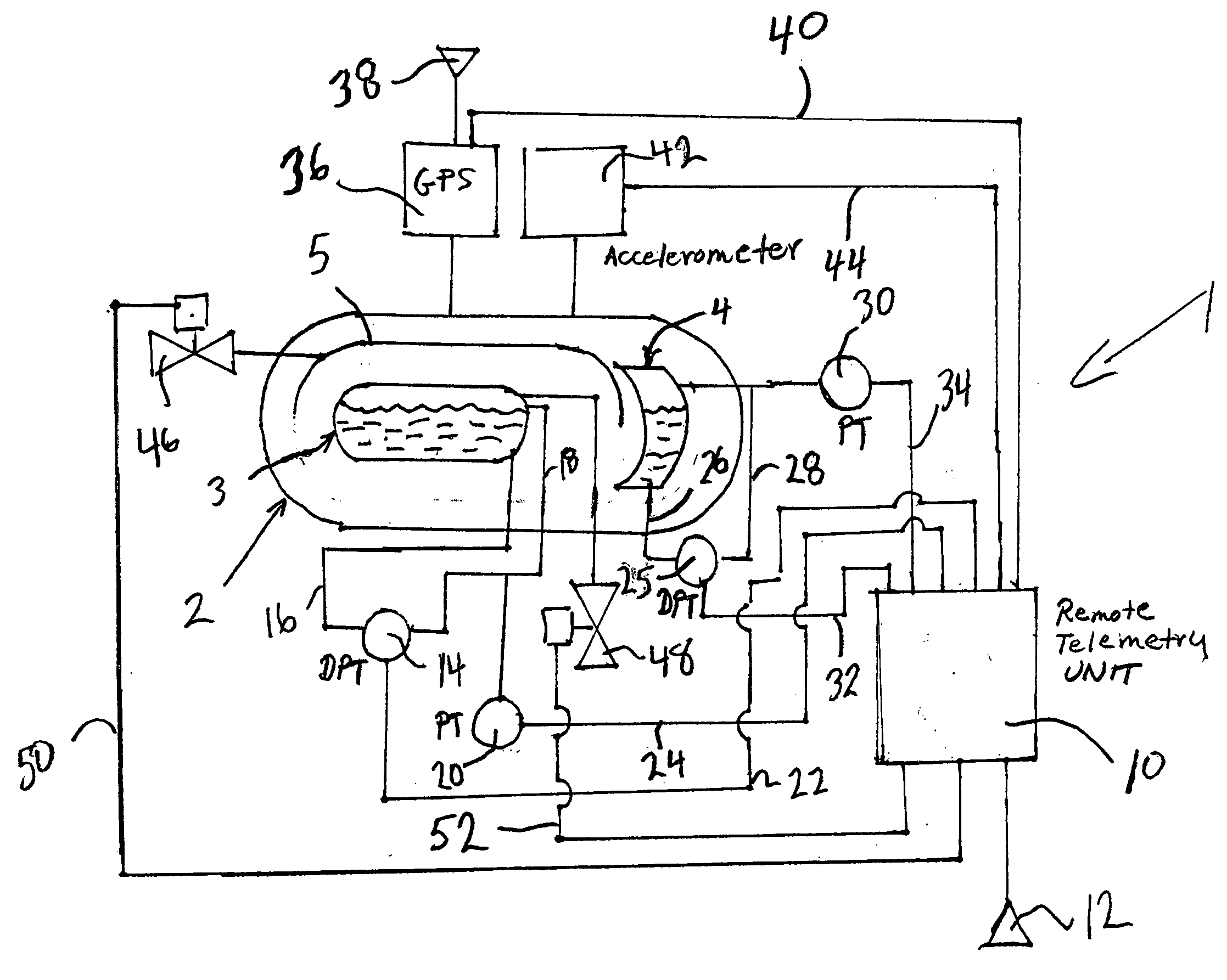
[0013] An accelerometer or multiple accelerometers can be provided to generate acceleration signals referable to a change in motion of the mobile storage tank. The remote telemetry unit is response to the acceleration signals and data records also comprise acceleration data referable to the change in motion of the mobile storage tank. The advantage of such a feature is that it allows remote operators to rapidly detect accidental handling that might lead to future failure of the mobile storage tank.

Problems solved by technology

Although such mobile storage tanks are heavily insulated and contain layers of vacuum insulation, heat leakage by radiant heat transfer causes vaporization of the liquefied gas during shipment.
The warm vaporized gas is vented and thereby results in product loss.
As may be appreciated, due to unforeseen delays, mobile storage containers sometimes arrive at their destinations with a high percentage of product loss or empty.
For instance, during a lengthy ocean voyage, where the storage tank is in customs for too long a time, all the product may be lost.
In case of helium, this can be a particularly expensive loss.
The problem with implementing such a system with respect to a mobile storage tank is that by necessity, the mobile storage tank can only be provided with on-board battery and / or solar power.
Thus, the use of a remote telemetry unit in the same manner as in a fixed installation is not practical.
Additionally, even with the use of a remote telemetry unit, mere transmission of pressure, content level, and / or temperature data are not very useful if the location of the mobile storage tank is not known.

Method used


Image

  • Monitoring system for a mobile storage tank
  • Monitoring system for a mobile storage tank
  • Monitoring system for a mobile storage tank

Examples


Embodiment Construction

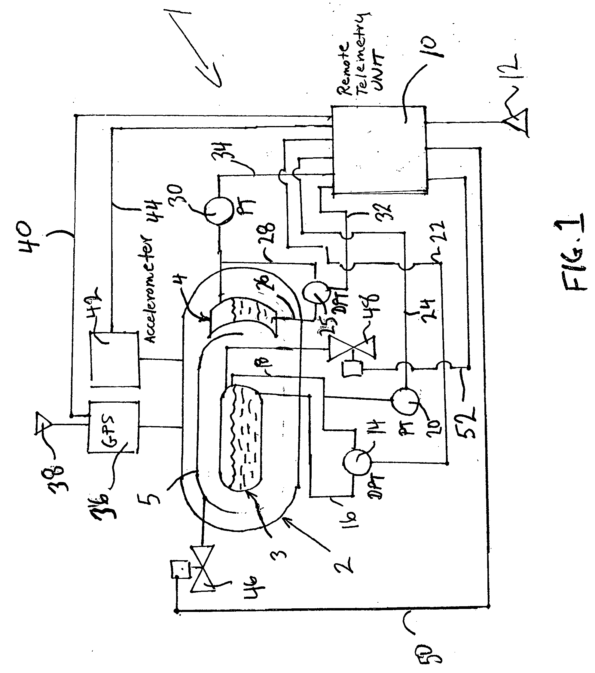
[0023] With reference to FIG. 1 remote monitoring system 1 is illustrated in accordance with the present invention. Remote monitoring system 1 is used to monitor the conditions within the mobile storage tank 2 having a product container 3 that is designed to transport helium and a shield fluid tank 4 designed to contain a cryogenic shield fluid, such as nitrogen. The nitrogen cools a thermal shield 5 located within a vacuum insulation layer surrounding the product container 3 to intercept some of the radiant heat that would otherwise pass to product container 3 and heat the helium.

[0024] As will be discussed, although the present invention is described with respect to the transportation of helium and the use of thermal shield, it has broader application to any mobile storage tank having a product container that stores a liquefied gas at cryogenic temperatures for transport.

[0025] Although not illustrated, but as well known in the art, thermal shield 5 is formed by a curved rectang...


PUM


Abstract

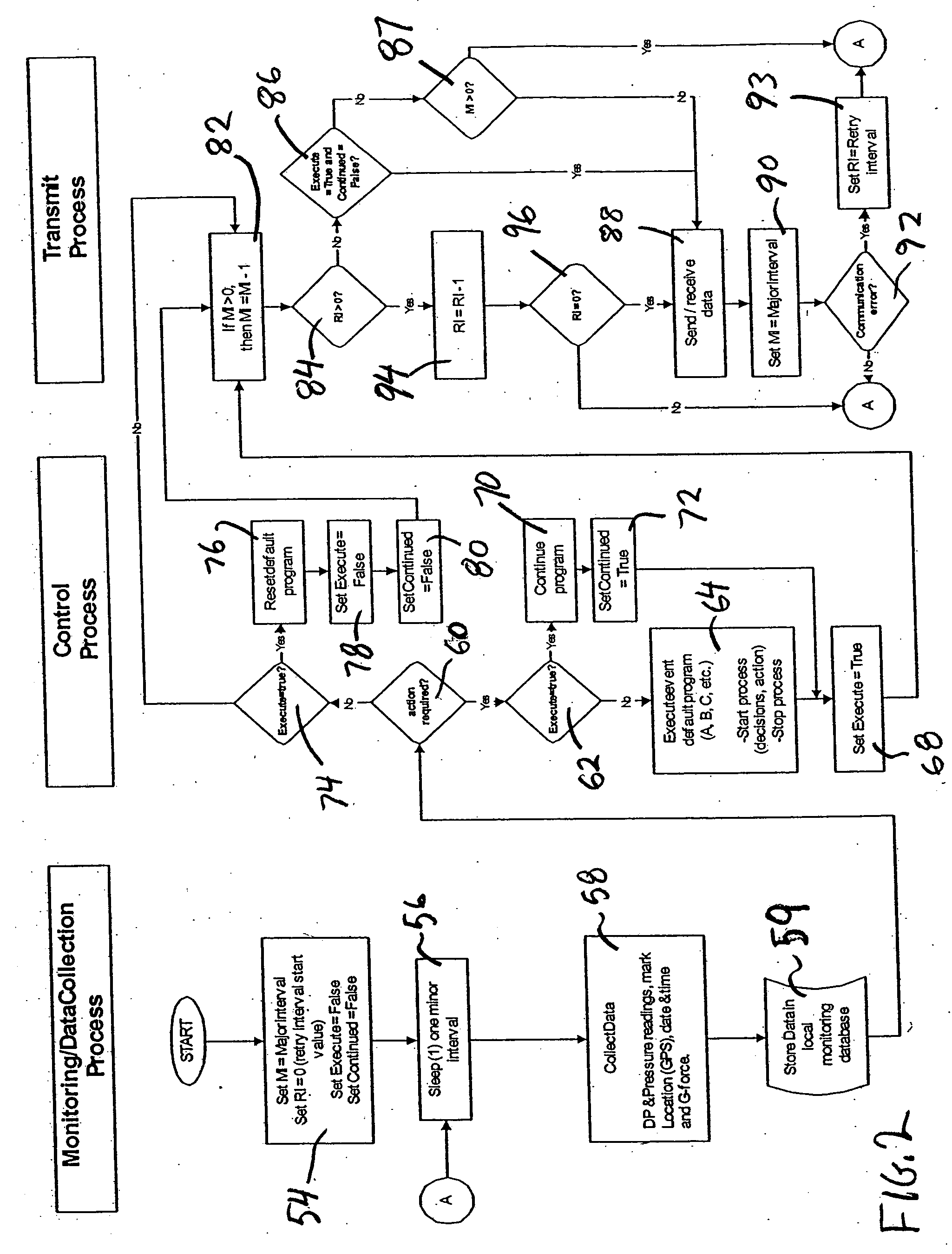
A remote monitoring system for a mobile storage tank having a product container in which a remote telemetry unit gathers liquid level and head space pressure data and global position data. The remote telemetry unit effects a wireless transmission of a standard message structure containing the pressure and level data and the global position data. In addition, in case of a storage tank having a thermal shield fluid, pressure and level data for the shield fluid itself may also be in the standard data record as well as acceleration data from an accelerometer to indicate tank damage. If upset conditions of pressure and liquid level are reached in the thermal shield and / or product container, vapor may be vented in accordance with preset programming in order to attempt to reestablish liquid level and vapor pressure above set points.

Description

FIELD OF THE INVENTION [0001] The present invention relates to a remote monitoring system for a mobile storage tank in which a liquefied gas is stored within a product container at cryogenic temperatures. More particularly, the present invention relates to such a system in which data records of liquid level and vapor pressure within the product container along with global position data derived from a global positioning system are stored in and subsequently transmitted from a remote telemetry unit to a receiving station. BACKGROUND OF THE INVENTION [0002] Liquefied gases, such as liquid nitrogen, liquid oxygen, helium, hydrogen and etc., are stored at cryogenic temperatures within mobile storage tanks for shipment to customers. Such mobile storage tanks are incorporated into truck drawn trailers, rail cars, and sea going tanks. [0003] Although such mobile storage tanks are heavily insulated and contain layers of vacuum insulation, heat leakage by radiant heat transfer causes vaporiza...

Claims


Application Information

Patent Timeline
Patent Type & Authority Applications(United States)
IPC IPC(8): B60Q1/00F17C13/02G08B1/08G08C17/02H04Q9/00
CPCF17C13/02F17C2270/0168H04Q9/00Y02E60/321H04Q2209/40H04Q2209/883F17C2205/0326F17C2221/011F17C2221/012F17C2221/014F17C2221/017F17C2223/0161F17C2223/033F17C2250/034F17C2250/0408F17C2250/043F17C2250/0482F17C2250/072G08C17/02Y02E60/32G08B1/08B60Q1/00
Inventor BULIN, TOMGALLAGHER, TOMGRAY, SCOTT E.LANGTON, GERARD W.
Owner PRAXAIR TECH INC
Learn More