Electrochemical cell closure

a technology of electrochemical cells and cell closures, applied in the field of electrochemical cells, can solve the problems of reducing the amount of cell housings, caps, seal materials, etc., and achieve the effect of high capacity, cell capacity can be increased, and high capacity

Inactive Publication Date: 2005-07-07
THE GILLETTE CO
View PDF14 Cites 3 Cited by
  • Summary
  • Abstract
  • Description
  • Claims
  • Application Information

AI Technical Summary

Benefits of technology

[0003] In general, the invention features an electrochemical cell having a high capacity. The cell capacity can be increased by a method of selecting cell components to achieve particular volume ratios within the cell. Specific volume ratios that lead to high capacity include the ratio of the internal cell volume to the external volume, the ratio of the closure volume to the external volume, the ratio of the closure volume to the internal cell volume, the ratio of the seal volume to the internal cell volume, and the ratio of the seal volume to the external volume. Using the method, cells having improved capacity, while maintaining safety features, can be prepared. In addition, the method can lead to a decrease in the amount of housing, cap, and seal material used in the cell.

Problems solved by technology

In addition, the method can lead to a decrease in the amount of housing, cap, and seal material used in the cell.

Method used


Image

  • Electrochemical cell closure
  • Electrochemical cell closure
  • Electrochemical cell closure

Examples


examples 1-5

[0024] Table 1 lists some of the dimensions of the cell components used to prepare five different cell sizes. Example 1 is a D size cell, Example 2 is a C size cell, Example 3 is a AA size cell, Example 4 is a AAA size cell, and Example 5 is a AAAA size cell.

TABLE 1Example 1Example 2Example 3Example 4Example 5Internal Volume (cc)42.3619.686.282.891.65Overall Height (mm)60.3849.3750.1544.242Housing Outer Diameter32.9225.2113.9210.167.85(mm)Cell Closure Height (mm)17.997.624.574.254.15Can Wall Thickness (mm)0.250.250.230.2030.203Pip Thickness (mm)0.250.250.250.2030.203Cathode Height (mm)47.841.3542.638.4234.65External Cell Volume (cc)56.49526.9568.3393.8532.299log10 (External Volume)1.75201.43060.92110.58580.3615Cell Diameter (mm)34.226.614.510.28.3Closure Volume (cc)3.6051.9730.4320.2180.18Seal Volume (cc)1.0560.6620.1180.0600.041Seal Volume / External1.872.461.421.571.79Volume (%)Closure Volume / External6.387.325.185.667.83Volume (%)Internal Volume / 74.9873.0175.3175.0171.77External V...

examples 6-11

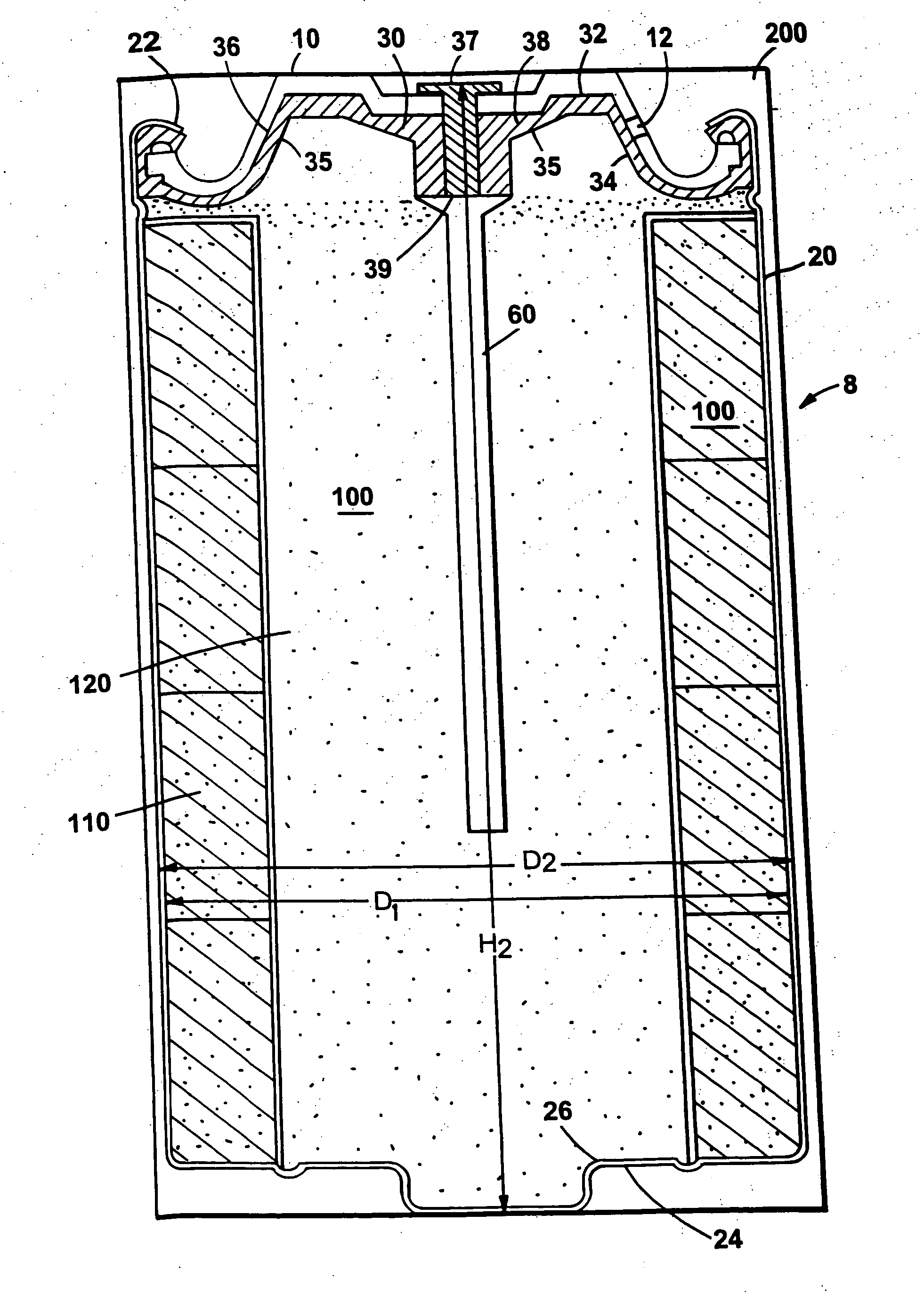
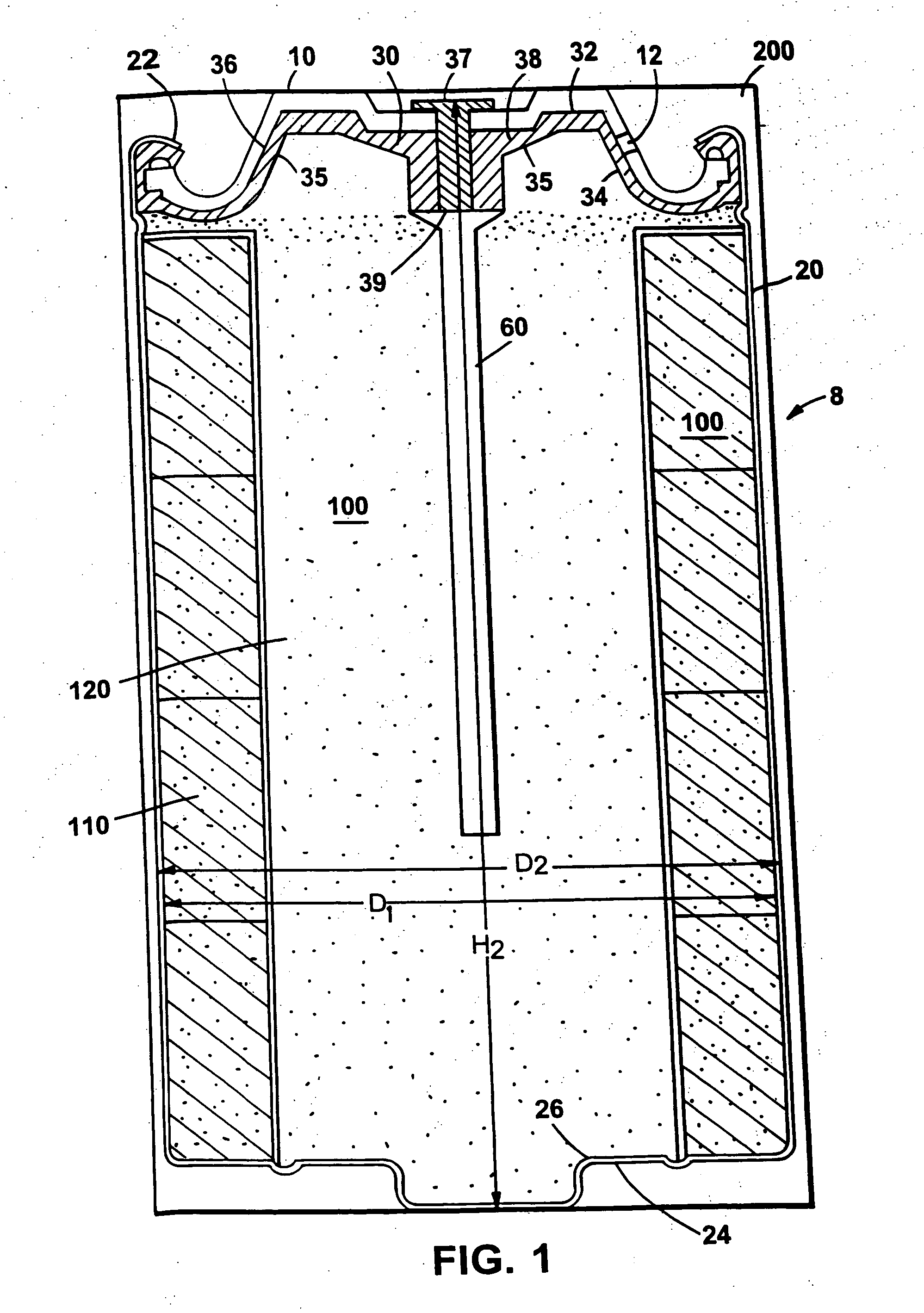
[0031] A set of cells was prepared selecting cell closures and insulating seals having smaller volumes than in Examples 1-5. For example, the AA size cell seals were thinned from a volume of 0.432 cubic centimeters to a volume of 0.120 cubic centimeters. In Examples 6 and 7, the larger volume seals had the structure described in U.S. Pat. No. 5,080,985 and U.S. Pat. No. 5,750,283. In Examples 8-11, the smaller volume seals had the structure describe in U.S. Ser. No. 09 / 047,264, filed Mar. 24, 1998. In general, the seal volume was reduced by lining the seal up against the end cap, as depicted in FIG. 1, so that the cap can support and replace thick structural areas of previous seal designs. The seal depicted in FIG. 1 represents the general design of the family of seals used in Examples 8-11.

[0032] The cans of Examples 6 and 7 were 0.010 inches thick. The cans of Examples 8-11 were 0.008 inches thick. In the AA cells (Examples 8 and 10), the cans were 0.203 mm thick. In the AAA cell...


PUM

PropertyMeasurementUnit
diameteraaaaaaaaaa
diameteraaaaaaaaaa
diameteraaaaaaaaaa

Abstract

An electrochemical cell having a high capacity is described. The cell capacity can be increased by a method of selecting cell components to achieve particular volume ratios within the cell. Specific volume ratios that lead to improved capacity include the ratio of the internal cell volume to the external volume, the ratio of the closure volume to the external volume, the ratio of the closure volume to the internal cell volume, the ratio of the seal volume to the internal cell volume, and the ratio of the seal volume to the external volume.

Description

BACKGROUND OF THE INVENTION [0001] This invention relates to electrochemical cells. [0002] Electrochemical cells, such as alkaline batteries, are commonly used as energy sources. Generally, alkaline batteries have a cathode, an anode, a separator, and an alkaline electrolyte solution. The cathode is typically formed of a cathode material such as manganese dioxide, carbon particles, alkaline electrolyte solution, and a binder. The anode can be formed of a gel including alkaline electrolyte solution and an anode material such as zinc particles. The separator is disposed between the cathode and the anode. The electrolyte solution, which is dispersed throughout the battery, can be a hydroxide solution such as aqueous potassium hydroxide. The capacity of the electrochemical cell is related to the amount of anode material and cathode material that can occupy the cell within the physical and chemical constraints of the cell and electrochemical performance parameters. SUMMARY OF THE INVENTI...

Claims


Application Information

Patent Timeline
Patent Type & Authority Applications(United States)
IPC IPC(8): H01M2/04H01M2/08H01M2/12H01M6/08H01M2/02H01M6/50H01M10/24
CPCH01M2/022H01M2/0417H01M6/08Y10T29/4911H01M2006/5094Y10T29/49108H01M6/085H01M50/107H01M50/154Y02P70/50
Inventor SARGEANT, SEAN A.HAMILTON, TERRY L.
Owner THE GILLETTE CO
Why Eureka
Try Eureka