Radio-controlled clock and method for determining the beginning of a second from a transmitted time signal

a radio-controlled clock and transmitted time technology, applied in the field of radio-controlled clocks and methods for determining the beginning of a second from transmitted time signals, can solve the problems of interference signals, inability to correctly recognize and evaluate the second markers of signals, and inability to receive time signals that are obscured or falsified, etc., to achieve simple regulation, improve system sensitivity, and reduce the rate of occurrence of errors due to falsified time durations

Inactive Publication Date: 2005-07-07
ATMEL GERMANY +1
View PDF4 Cites 23 Cited by
  • Summary
  • Abstract
  • Description
  • Claims
  • Application Information

AI Technical Summary

Benefits of technology

[0033] A further particular advantage of the invention thus exists in providing a simple regulating arrangement for compensating any possibly occurring offset using only previously existing circuit components and the like. In order to compensate an inexact start and thus deviations of the reference clock from a prescribed 
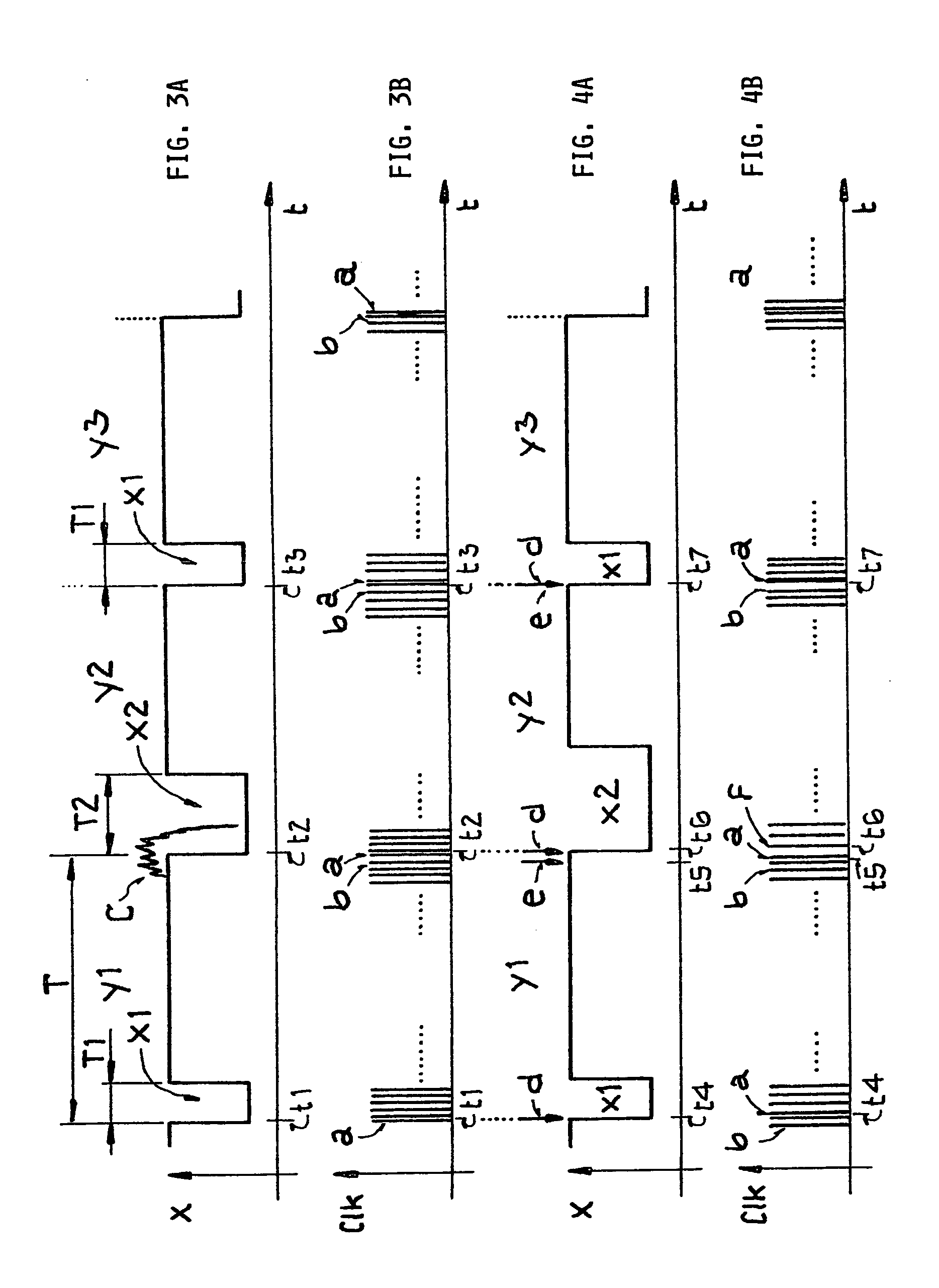
time marker (for example the second beginning) of the received time signal, the invention provides a compensation circuit that followingly regulates or regulates-out this deviation. Such a regulation operates as follows. If, for example, in a time frame being considered, the actual second beginning occurs earlier than the calculated second beginning, then for determining the second beginning in one of the subsequent time frames at least one clock pulse is skipped (or omitted or not considered), so that the second beginning calculated for this time frame is advanced by the time duration of one clock pulse. On the other hand, if the calculated second beginning comes after the actual second beginning, then an additional clock pulse is inserted for at least one of the subsequent time frames, so that the second beginning calculated for the corresponding time frame is delayed by the duration of one clock pulse or cycle. In this manner, a very simple regulation can be implemented.
[0034] The receiver circuit, or the corresponding radio-controlled clock having such a receiver circuit, according to the invention, advantageously have a higher system sensitivity, because interferences at the beginning of a respective time frame are not taken into consideration. Falsifications of the time duration of the amplitude variation can advantageously be avoided by the regulating arrangement described above. Thus, the rate of occurrence of errors due to falsified time durations of an amplitude variation caused by interference pulses is significantly reduced, which ultimately leads to a greater sensitivity of the receiver circuit. The above described purely digital regulation for the compensation of an offset or a deviation in the determination of the second beginning makes external circuit components and tolerance-influenced analog circuit parts superfluous. In this manner, the advantage gained through the above described regulation or compensation is not again eradicated through tolerances of the circuit components. Moreover, the receiver circuit may additionally be relatively simply implemented, because the purely digital regulation can be carried out, for example, by the micro-controller that is present anyway in the radio-controlled clock. The regulation itself requires a relatively small computational effort, so that the other functioning of the micro-controller is only insignificantly impaired by additionally carrying out the regulation.
[0035] For determining the second beginning of a time frame, advantageously the time counting by the counter is carried out from the second beginning of the immediately, i.e. directly, preceding time frame. This is especially recommendable in terms of the circuit technology, because the counter in this case can again be reset and newly restarted respectively at the end of each time frame. This makes it possible to use a simple low bit counter.
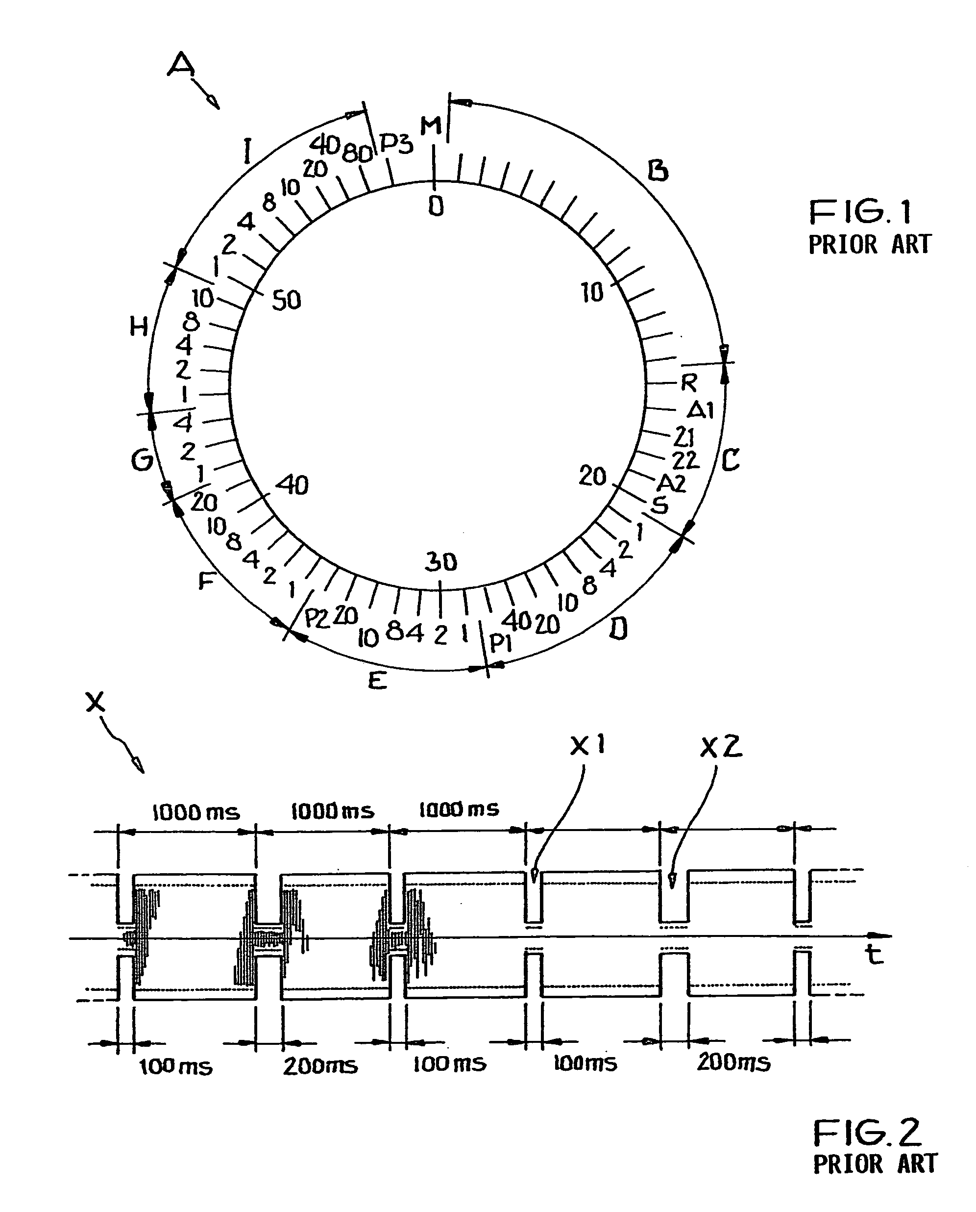
[0036] When a time signal is received for the first time, an actual second beginning is at first not known. However, as described above, in order to determine the second beginning of subsequent time frames according to the invention, an actual second beginning must at first be determined at least one time, and thereafter the subsequent second beginnings of subsequent time frames can be determined, i.e. calculated, according to the invention. For this purpose, the beginning of a first change or variation of the received time signal is at first determined. Then, the duration of a signal amplitude variation is counted-up by the counter. In this regard, the duration of the amplitude variation must be one of only a few possible prescribed durations, and is known from the telegram of the time signal. In this manner, by comparing the detected signal amplitude variation to the known duration, it can be ensured that this first signal amplitude variation is not simply (and falsely) an interference in the time signal. If this has been unambiguously recognized and determined, and a second new amplitude variation of the signal course of the time signal occurs after approximately 1 second following the beginning of the first signal amplitude variation, then the detected beginning of the second new variation is valued or taken (i.e. specified) as a true or actual second beginning. Additionally or alternatively, a method as disclosed in the above mentioned Patent Publications DE 195 14 036 C2 or DE 37 33 965 C2 can be used for determining the first actual second beginning.
[0037] Advantageously, the time duration of a time frame is determined by counting the clock pulses of a reference clock signal. This reference clock signal has a known, i.e. prescribed, reference frequency. A clock signal or timing pulse signal with the most constant possible prescribed clock frequency is advantageously used as the reference clock signal or timing pulse signal, which thus has a prescribed number of clock pulses or timing pulses per time frame.
[0038] The reference clock signal is preferably a clock signal or timing pulse signal in which the duration of each timing pulse or clock cycle ideally is less than 10% of the duration of the shortest signal amplitude variation prescribed by the telegram of the time signal, i.e. the temporally shortest second marker. Thus, there will be at least ten clock pulses of the reference clock signal during the duration of the shortest signal variation representing a second marker. Ideally and most preferably, the duration of the reference clock cycle amounts to less than 5% of the duration of the shortest time signal variation. For example, if a reference clock signal with a reference frequency of 128 Hz is used (this corresponds to approximately the {fraction (1 / 256)}th portion or fraction of the frequency of a quartz clock oscillator), and if a time frame amounts to approximately one second, then the counter will have to count-up exactly 128 clock pulses or cycles for determining the timed or calculated second beginning of the next successive time frame. In that regard, a single clock pulse or cycle corresponds to about 7.8 ms.

Problems solved by technology

In this regard it is problematic that the received time signals can be obscured or falsified by interference signals superimposed thereon.
Such interference signals arise from the interference fields emitted by electrical or electronic devices, for example in the direct surrounding vicinity of the time signal receiver.
Depending on the type, scope and strength of these interference signals, the reception of the time signal will be more or less interfered with, and it may become impossible to correctly recognize and evaluate the second markers of the signal.
The conventional method according to DE 37 33 965 C2 suffers a significant disadvantage, however, in that a signal acquired from the signal courses or progressions of several time frames must be compared with a model signal in order to achieve the synchronization of the radio-controlled clock to the second beginning.
Moreover, carrying out the comparison as mentioned above also requires an extremely high expenditure of computational time and effort.
However, such correspondence of the received time signal with the transmitted time signal occurs relatively seldom or infrequently in actual practice.
These interference signals, which typically arise in the transmission path between the time signal transmitter and the radio-controlled clock receiver, and also within the receiver section of the radio-controlled clock itself, can occasionally very strongly or sharply change and thus falsify the signal form of the transmitted time signal.
This interference problem can even go so far, that at the actual second beginning, the received time signal has such a strong interference pulse superimposed thereon, that the actual second beginning can no longer be correctly determined or derived from the sampled signal curve course or progression of the signal amplitude.
Thus, in such a situation, the above described conventional methods for determining the second beginning will determine a second beginning that is offset or time-shifted after or even before the actual second beginning occasionally it can also arise, that the time signal is superimposed with such a strong interference pulse during the duration of an amplitude dip (i.e. representing a second marker), such that the second beginning of the current time frame cannot be detected at all, which ultimately leads to the result that the corresponding data bit cannot be decoded at all.
In disadvantageous cases it can also arise that the corresponding data bit is erroneously decoded and evaluated due to the time offset or time shifting of the second beginning that has been determined from the sampled values.
This can directly lead to a determination and indication of an incorrect time.

Method used


Image

  • Radio-controlled clock and method for determining the beginning of a second from a transmitted time signal
  • Radio-controlled clock and method for determining the beginning of a second from a transmitted time signal
  • Radio-controlled clock and method for determining the beginning of a second from a transmitted time signal

Examples


Embodiment Construction

[0053] In all of the drawing figures, the same elements and signals, as well as the elements and signals respectively having the same functions, are identified by the same reference numbers, unless the contrary is indicated.

[0054] The general format of an encoding scheme or time code telegram A as conventionally known in the time signal transmitted by the German time signal transmitter DCF-77 has been explained above in connection with FIG. 1 in the Background Information section of this specification. Also, the time-variation of the amplitude-modulated time signal is schematically shown in the time diagram of FIG. 2 as discussed above.

[0055] The schematic time diagrams of FIGS. 3A and 3B show a portion of a time signal X and the corresponding timing pulses of a reference clock signal CLK in connection with which the inventive method for determining the second beginning will now be explained. As an example, FIG. 3A shows the time signal X transmitted by the German time signal tran...


PUM


Abstract

A transmitted time signal carries encoded time information in a succession of time frames of constant duration. An amplitude variation of the time signal indicates the beginning of a second within a time frame, but may be obscured by interference. Once an actual second beginning is known, e.g. unambiguously detected without interference, then a counter counts up a prescribed number of timing pulses of a reference clock signal to calculate the next expected second beginning of the next time frame. If the next actual second beginning is obscured by interference, then the calculated second beginning is used, otherwise the next actual second beginning can be used, in the decoding and evaluation of the time information. The counter is reset and counts up to calculate the successive next expected second beginning. A circuit for performing this method includes a signal form evaluating unit, a counter, a regulating unit and a reference clock signal generator.

Description

PRIORITY CLAIM [0001] This application is based on and claims the priority under 35 U.S.C. §119 of German Patent Application 103 61 593.8, filed on Dec. 30, 2003, the entire disclosure of which is incorporated herein by reference. FIELD OF THE INVENTION [0002] The invention relates to a method for determining the beginning of a second from a transmitted time signal containing time information, as well as a radio-controlled clock and its receiver circuit for carrying out such a method. BACKGROUND INFORMATION [0003] It is conventionally known to provide time reference information in time signals that are transmitted by radio transmission from a time signal transmitter. Such a signal may also be called a time marker signal, a time data signal, a time code signal, or a time reference signal, for example, but will simply be called a time signal herein for simplicity. The time signal transmitter obtains the time reference information, for example, from a high precision atomic clock, and b...

Claims


Application Information

Patent Timeline
Patent Type & Authority Applications(United States)
IPC IPC(8): G04F5/00G04G5/00G04R20/12H04L12/50
CPCG04R20/12G04G5/002
Inventor HAEFNER, HORSTPOLONIO, ROLANDSAILER, HANS-JOACHIM
Owner ATMEL GERMANY
Why Eureka
Try Eureka