Energization cycle counter for induction heating tool

a technology of induction heating and cycle counter, which is applied in the field of counting sensors, can solve the problems of stress cracks and coil damage, limited life cycle of joints, and damage to the coil, so as to reduce overall production costs, reduce inventory, and optimize production

Active Publication Date: 2005-07-07
AJAX MAGNETHERMIC CORP
View PDF29 Cites 0 Cited by
  • Summary
  • Abstract
  • Description
  • Claims
  • Application Information

AI Technical Summary

Benefits of technology

[0011] The present invention provides an induction heat treating process with a sensor for counting the amount of cycles attributable to an individual inductor coil. Additionally, the sensor may be used to count the duration of energization of a coil, or both. The sensor is preferably a counting mechanism attached to or embedded within the induction heating coil or bus bar and is triggered by and responds to the change in voltage generated as the coil is energized. Alternative designs may measure current, magnetic field, frequency and / or temperature differentials on each individual coil. Additionally, the sensor may be an identifier or tag attached to or embedded within the induction heating coil or bus bar assembly that signals an indicator to an external data maintenance source, such as a control cabinet or personal computer for example, to register a consecutive count of cycles or duration of energization or both for the identified coil. The data culled from the sensor or other data maintenance and retrieval sources provides useful information for determining the lifespan of an induction heating coil. Predicting the lifespan of a coil optimizes production by anticipating failure and replacement of a coil during a predetermined down time, limiting on-site inventory, and revolutionizing the repair billing cycle based on a per cycle cost while decreasing overall production costs.
[0013] Once an average baseline lifespan for each coil design is established, whether on a per cycle or duration basis, the monitoring system of the present invention can provide useful information to optimize the operation of each induction heating machine and overall production. The monitoring system includes providing an induction heating coil with a counting sensor attached or embedded within each coil. Preferably, a coil monitoring company provides an induction heating coil with sensor for lease, rather than purchase, by a company for use during production. As the sensor tallies cycles or duration for each coil, the coil monitoring company as proprietor of the monitoring system reads the output from the sensor and compares the total cycles or duration to the baseline lifespan of each coil design. When a predetermined threshold cycle count or duration period is met, the coil monitoring company as part of the overall monitoring system notifies the leasing company of an anticipated need to change a coil before failure. Once removed from the induction heating machine, the coil is preferably forwarded to the coil monitoring company for analysis and distribution to a coil manufacturing company for repair and reuse. Alternatively, the coil monitoring company may repair induction heating coils in-house. The leasing company is charged for each cycle or segment of time experienced by the induction heating coil and does not incur the cost of repair.
[0014] Additionally, the system of the present invention provides an efficient method for monitoring on-site induction heating coil inventory. An induction heating machine using multiple designed coils for hardening various workpieces during production may require the removal of one coil design and replacement with a second coil design. When production using the first coil design resumes, the counting system provides a method for reading the output from each coil sensor. This application is also advantageous when induction heating coils are used in series for continuous heat treating of billets prior to stamping. In a preferred embodiment, a hand held reading device such as a bar code reader or personal computer is used to read and analyze the tallied count or duration period for each inventoried coil. Alternatively, an LED readout may be provided within the counter mechanism and activated by the push of a button for viewing the number of cycles or duration period applicable to a particular coil. This educates the operator as to which coil best suits the needs of current production. The system also aids the operator in determining which coil should be used to replace the failed or failing coil in the examples set forth above. With this information the operator can predict and prepare for scheduled coil changeovers to eliminate production downtime.
[0015] When the failed coils are returned for repair, the coil monitoring company through the monitoring system, further provides a method for establishing industrial standards for induction heating coils. The coil monitoring company through the data culled from the monitoring system will maintain a database for recording the cycle lifespan or duration period of a certain coil design and the area of failure, for example. This information is accumulated and can aid in possibly improving the coil design by eliminating repetitive failure areas such as unnecessary or poorly brazed joints or use of inferior brazing material.
[0016] The coil monitoring company through monitoring system also provides a means for renovating the costs associated with current production processes. Instead of purchasing induction heating coils and contracting for repair, the monitoring system provides a method for leasing induction heating coils and paying on a per cycle basis. Alternatively, payment may be based on a time basis when the induction heating coil is measured for duration of energization. A fixed per cycle or time bases cost will encourage coil manufacturers to manufacture coils of the highest quality and maintain continuous improvement of production induction heating coils. This eliminates repair costs and provides a known fixed production price per part. By monitoring the lifespan of an induction heating coil, the system eliminates unknown costs, increases production, limits inventory, decreases potential waste costs and establishes industrial standards for the manufacturing and design of heating coils.

Problems solved by technology

Both conventional induction heat treating processes are detrimental to the perishable heat treating tool.
The joints have a limited life cycle and are prone to failure or leakage and must be repaired.
Further, arcing often occurs where there are small air gaps between the tool and the workpiece causing stress cracks and damage to the coil.
During continuous heat induction, the surrounding refractory material tends to breakdown due to the heat or other property failures.
These examples only exacerbate the already short tooling life of a coil and lead to costly repairs.
Tooling and production shutdown are costly and time-consuming.
Employing multiple coils with each machine, without knowing the cycle history of each individual coil increases the opportunity for production interruption.
More often than not, the end user will choose to send the coil to an after market company for the repair based mainly on the cost of the repair.
A costly inventory of inductor coils is maintained at the production site for immediate replacement when a coil fails during production.
However, no record is kept of how many times each individual inductor coil is energized, or cycled, or the duration of energization of the coil during a heating process.
These tool costs are incorporated into the overall cost of each manufactured part.
When an inductor coil fails, production stops.
If the parts do not meet the specified criteria, they are scrapped, resulting in an expensive waste of material and labor.
The alternative option is to wait until the metallurgical results are verified before running production, this may take hours.

Method used


Image

  • Energization cycle counter for induction heating tool
  • Energization cycle counter for induction heating tool
  • Energization cycle counter for induction heating tool

Examples


Embodiment Construction

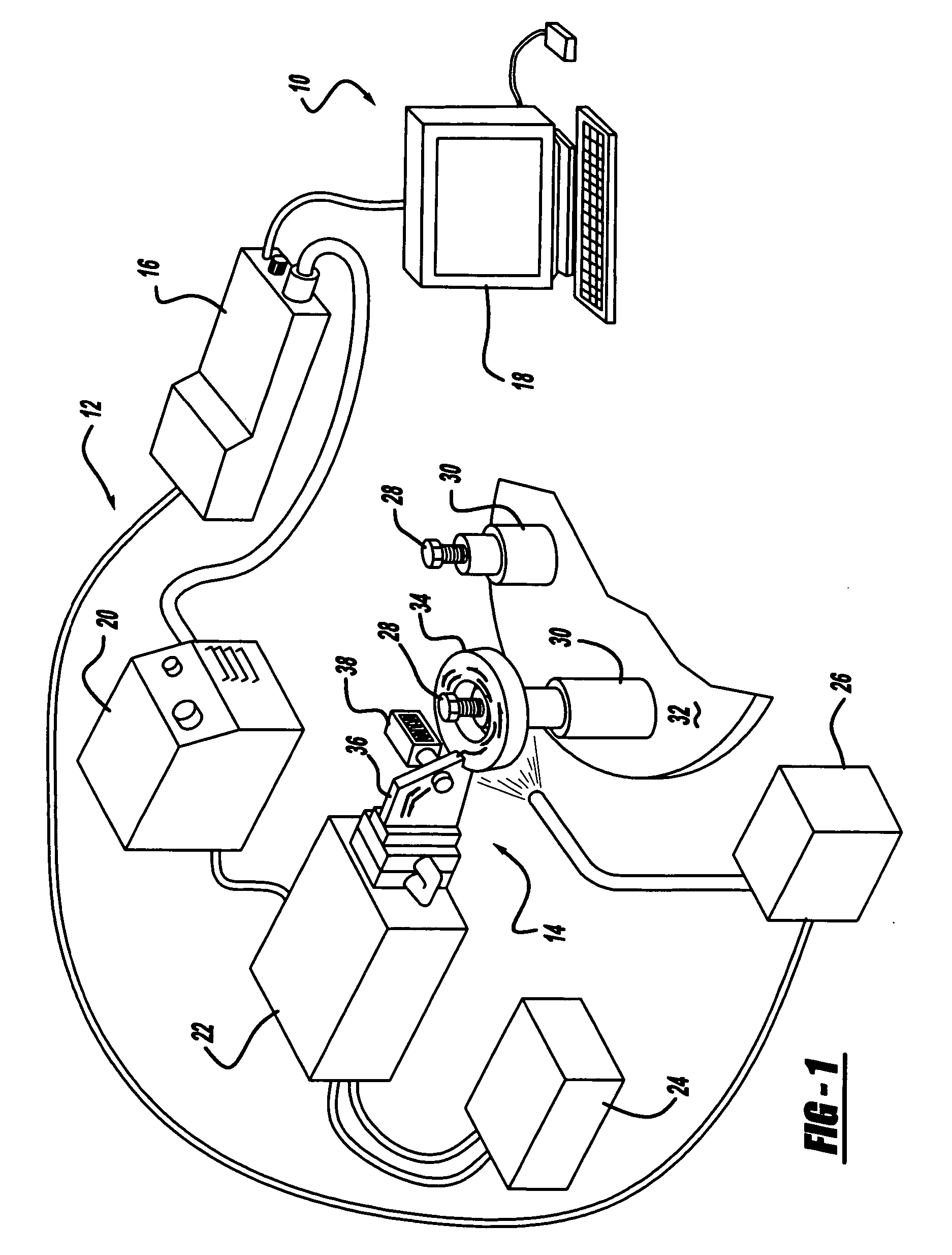
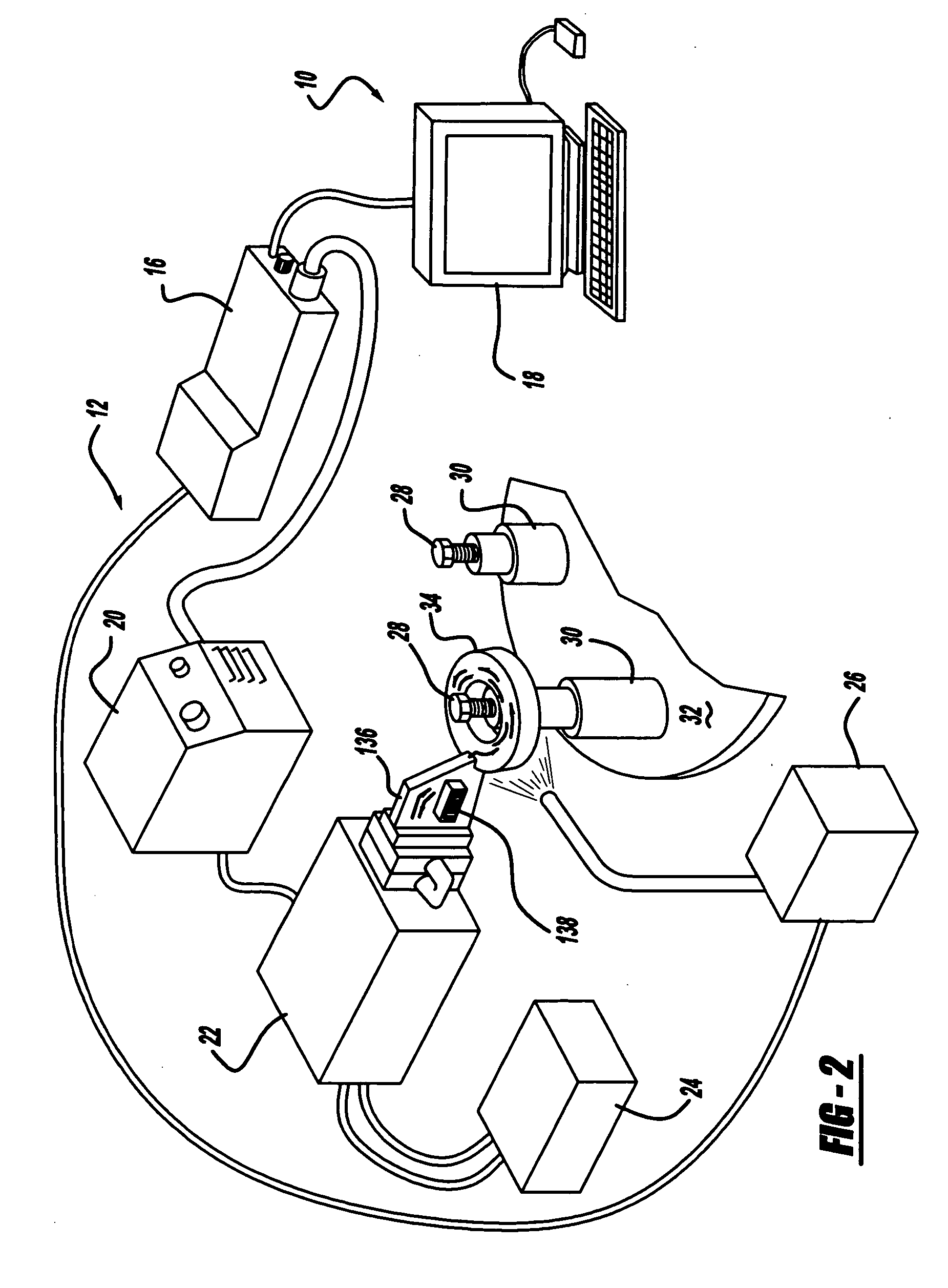
[0022] With reference to FIGS. 1 and 2, a monitoring system 10 of the present invention is there shown and includes an induction heating coil assembly 12 and subassembly 14. The components of the induction heating coil assembly 12 include a Program Learning Center (PLC) 16 connecting a hard-wired Personal Computer (PC) 18 with a power supply 20. In an industrial setting, the PLC 16 is connected to a control cabinet (not shown) for automation and control of the induction process. The personal computer 18 is illustrated as part of the assembly 12, however, the personal computer 18 may be located off premises and connected to the monitoring system 10 via the Internet or other well-known communication devices.

[0023] A transformer 22 is connected to the power supply 20 and connects the induction heating coil subassembly 14 to the monitoring system 10. A cooling unit 24 for cooling the transformer 22 and coil subassembly 14 during the induction heating process is provided along with a qu...


PUM


Abstract

An induction heat treating process with a sensor for monitoring the duration of energization of an induction heating coil each time the induction heating coil is consecutively cycled. The sensor is preferably a counting mechanism attached to or embedded within the induction heating coil and is preferably triggered by and responds to the change in voltage generated as the coil is energized. Alternative means of measuring a cycle may be implemented. The output data from the sensor provides useful information for determining the lifespan of an induction heating coil. Predicting the lifespan of a coil optimizes production by anticipating failure and replacement of a coil during a predetermined down time, limiting on-site inventory, and revolutionizing the billing cycle based on a per cycle cost while decreasing overall production costs and improving inductor coil quality.

Description

CROSS-REFERENCE TO RELATED APPLICATIONS [0001] This application is a continuation-in-part of U.S. application Ser. No. 10 / 750,640 filed on Jan. 2, 2004.TECHNICAL FIELD [0002] The present invention relates generally to a counting sensor for use in conjunction with an induction heat treating process. More particularly, the present invention relates to a system for counting the cycles of an individual inductor coil or the duration of energization of the induction heating coil or both and maintaining and transmitting this data to a remote unit location or self contained unit within the counting sensor. BACKGROUND OF THE INVENTION [0003] The induction heat treating process is used in various applications for hardening, and annealing of metals. The process includes applying energy directly to metals and other conductive materials via an alternating electric current passing through an induction heating coil positioned in close proximity to a workpiece. The induction heating process is appl...

Claims


Application Information

Patent Timeline
Patent Type & Authority Applications(United States)
IPC IPC(8): H05B6/06
CPCH05B6/06
Inventor BARTZ, KATHLEEN M.
Owner AJAX MAGNETHERMIC CORP
Why Eureka
Try Eureka