Eureka AIR delivers breakthrough ideas for toughest innovation challenges, trusted by R&D personnel around the world.

Autothermic packaging

a technology of autothermicity and packaging, which is applied in the direction of exothermal chemical reaction heat production, heat production devices, containers, etc., can solve the problems of insufficient air tightness, relatively weak seam, and difficulty in forming tight resistance connections,

Inactive Publication Date: 2005-07-07
ROMEU ISIDRO GENESCA
View PDF10 Cites 18 Cited by
  • Summary
  • Abstract
  • Description
  • Claims
  • Application Information

AI Technical Summary

Benefits of technology

[0017] Therefore, the airtightness between the first compartment, which contains the first chemical substance, and the receptacle containing the food substance, is guaranteed by said flanged and seamed mechanical join, which optionally can be reinforced with an elastic seal or an adhesive material, while the airtightness between the second compartment and the outside is guaranteed by said welding of the flanges of the heat insulating walls of the receptacle and the second compartment.

Problems solved by technology

One problem that, in general, the prior art autothermic packagings present is that the afore-mentioned seam is relatively weak and does not sufficiently guarantee the airtightness of the food product receptacle.
The problem is due to the difficulty in forming tight resistant connections between different materials that make up the walls of the various parts of the packaging.
These two materials cannot be joined together by thermal or ultrasonic welding, and normally special glues are used that do not provide a sufficiently secure join.
However, when the inside pressure and temperature increase, as in the case of an exothermic reaction, the fixation base of both materials becomes deformed and escape channels are created through which pressure from reheated steam produced by the reaction is released or, which is worse, through which the food product receptacle is contaminated.

Method used


Image

  • Autothermic packaging
  • Autothermic packaging
  • Autothermic packaging

Examples


Embodiment Construction

[0027] First of all, reference is made to FIG. 1 showing a basic embodiment of the autothermic packaging of this invention.

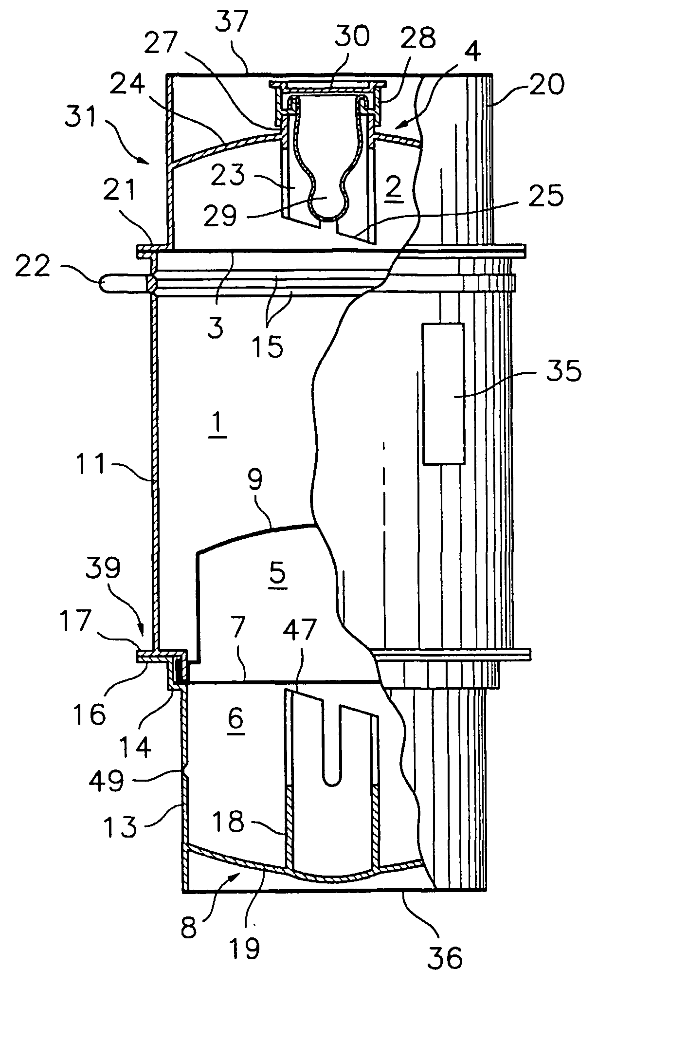
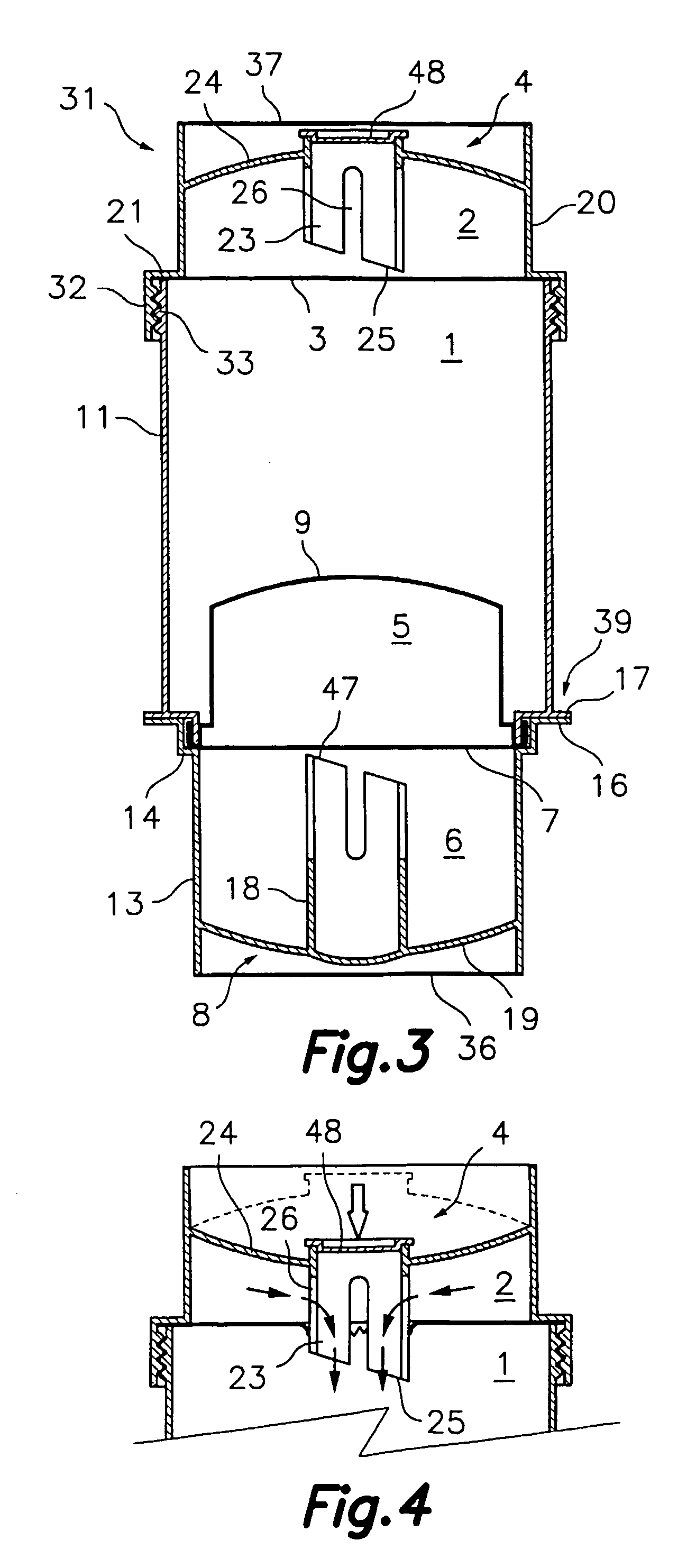
[0028] The autothermic packaging comprises a receptacle 1 for a food product, such as a drink or a meal in a liquid base. In the lower part of receptacle 1 there is a first compartment 5 containing a first substance that can react with a second substance contained in a second compartment 6, or undergo a phase change when exposed to conditions present in said second compartment 6, as explained below. The said first and second compartments 5, 6 back onto one another at their openings and they are separated by a breakable sheet 7 (e.g. a sheet of plasticized aluminium) which can be broken from the outside by penetration means 8 to produce a mixture and subsequent chemical reaction between said first and second substances, including heat exchange. Receptacle 1 and first compartment 5 have a common heat conducting wall 9 to facilitate the heat exchange therebetween....


PUM


Abstract

The invention relates to autothermic packaging comprising a container (1) for a food product and a first compartment (5) containing a first substance which can react with a second substance that is contained in a second compartment (6) or which can change phases when exposed to conditions in said second compartment (6). Both of the aforementioned compartments (5, 6) abut one another by means of the mouth thereof and are separated by means of a sheet (7) which can be broken from the outside using penetration means (8). At least one heat-conducting wall (9) is shared by the container (1) and the first compartment (5). Moreover, said heat-conducting wall (9) comprises a band (10) which is disposed next to the mouth thereof and the container (1) comprises an external heat-insulating wall (11) which is connected to a base member (39) having a band (12) close to a peripheral edge. The aforementioned peripheral flanged bands (10, 12) abut one another, thereby forming a hermetic, resistant seam by means of crimping.

Description

SCOPE OF THE INVENTION [0001] This invention relates to an autothermic packaging of the type comprising a receptacle for a food product and first and second compartments for one or more substances that can undergo a chemical or physical transformation via a heat exchange with respect to said receptacle, and means for voluntarily producing said chemical or physical transformation, causing said food product to be heated or cooled. BACKGROUND OF THE INVENTION [0002] For a long time it has been known to produce packagings for food products that incorporate in the actual packaging a receptacle for a food product or a drink and means for mixing two substances that can react, either exothermically or endothermically, and therefore produce a heat exchange with the container for heating or cooling the food product contained therein. [0003] In this sense, patent ES-A-423862 (SATO) applied for in 1974 can be mentioned, which describes several embodiments of a packaging for food products such a...

Claims


Application Information

Patent Timeline
IPC IPC(8): A47J36/28A61J9/00B65D51/28B65D81/32B65D81/34
CPCA47J36/28A61J9/00B65D81/3484A61J11/0095B65D81/3211A61J9/008
Inventor ROMEU, ISIDRO GENESCA
Owner ROMEU ISIDRO GENESCA
Why Eureka
Eureka Blog
Learn More