
Method and apparatus for manipulating a sample

a sample and sample technology, applied in the field of scanning probe microscopy, can solve the problems of nudge, difficult sample manipulation, present spms that do not provide an adequate mechanism for manipulating samples,

Inactive Publication Date: 2005-07-07
BRUKER NANO INC
View PDF4 Cites 27 Cited by
  • Summary
  • Abstract
  • Description
  • Claims
  • Application Information

AI Technical Summary

Benefits of technology

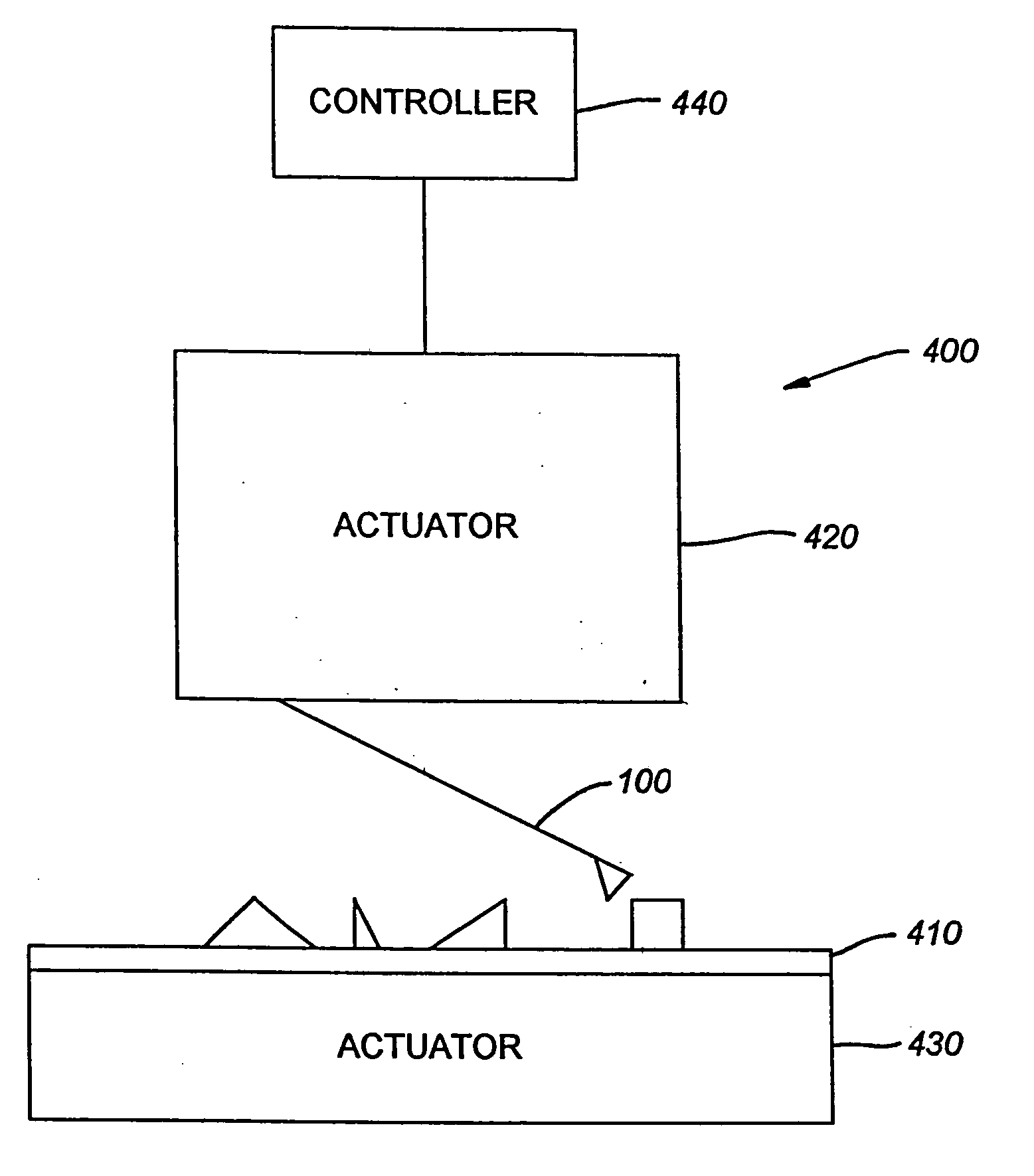
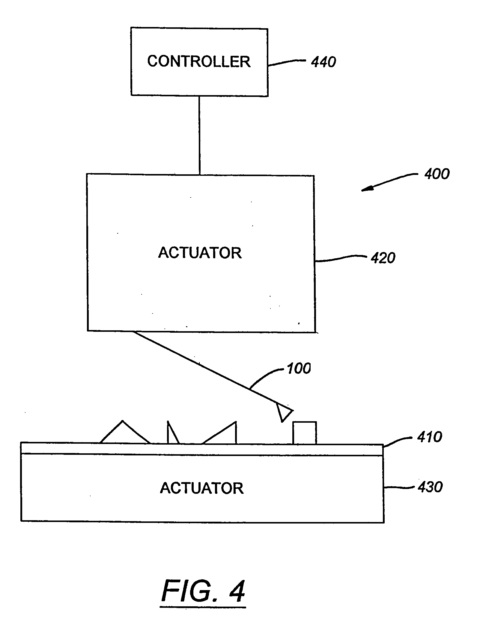
The present invention provides a method and apparatus for manipulating the surface of a sample using a probe that can perform both imaging and manipulation functions. The probe can be controlled independently, allowing for imaging with one probe while manipulating another probe. The tips of the probe can be opened and closed to pick up and drop objects on the sample surface, and can also provide electrostatic forces to the sample. The apparatus includes a scanning probe microscope with separate imaging and manipulation tips, and a nanomechanical tweezing apparatus with independently controlled tips. The method includes steps of turning off the feedback of the probe, lifting it from the surface, setting a deflection setpoint, and turning on the feedback to manipulate the surface. The technical effects include improved accuracy and efficiency in manipulating samples, as well as improved imaging capabilities.

Problems solved by technology

Unfortunately, present SPMs do not provide an adequate mechanism for manipulating the sample being imaged.
For example, present SPMs do not adequately provide for accurately picking up, nudging, etc. the sample or portions thereof.
Manipulation of the sample can be difficult because present SPMs do not allow for performing action on what often times are nanoscale objects.
This can create inaccuracies in determining the location of the manipulation probe with respect to an imaging probe because inaccuracies in offset determinations and inaccuracies in the precision of moving the probes.
This offset can result in errors when attempting to manipulate the sample.
Furthermore, present SPMs do not provide for adequate accuracy in manipulating particles on a sample due to limitations in the control accuracy of the actuator of the SPM.
Another difficulty is that present SPMs encounter drift in the relative positions of the tip and sample, which can result in a probe manipulating an incorrect position on the sample.

Method used


Image

  • Method and apparatus for manipulating a sample
  • Method and apparatus for manipulating a sample
  • Method and apparatus for manipulating a sample

Examples


Embodiment Construction

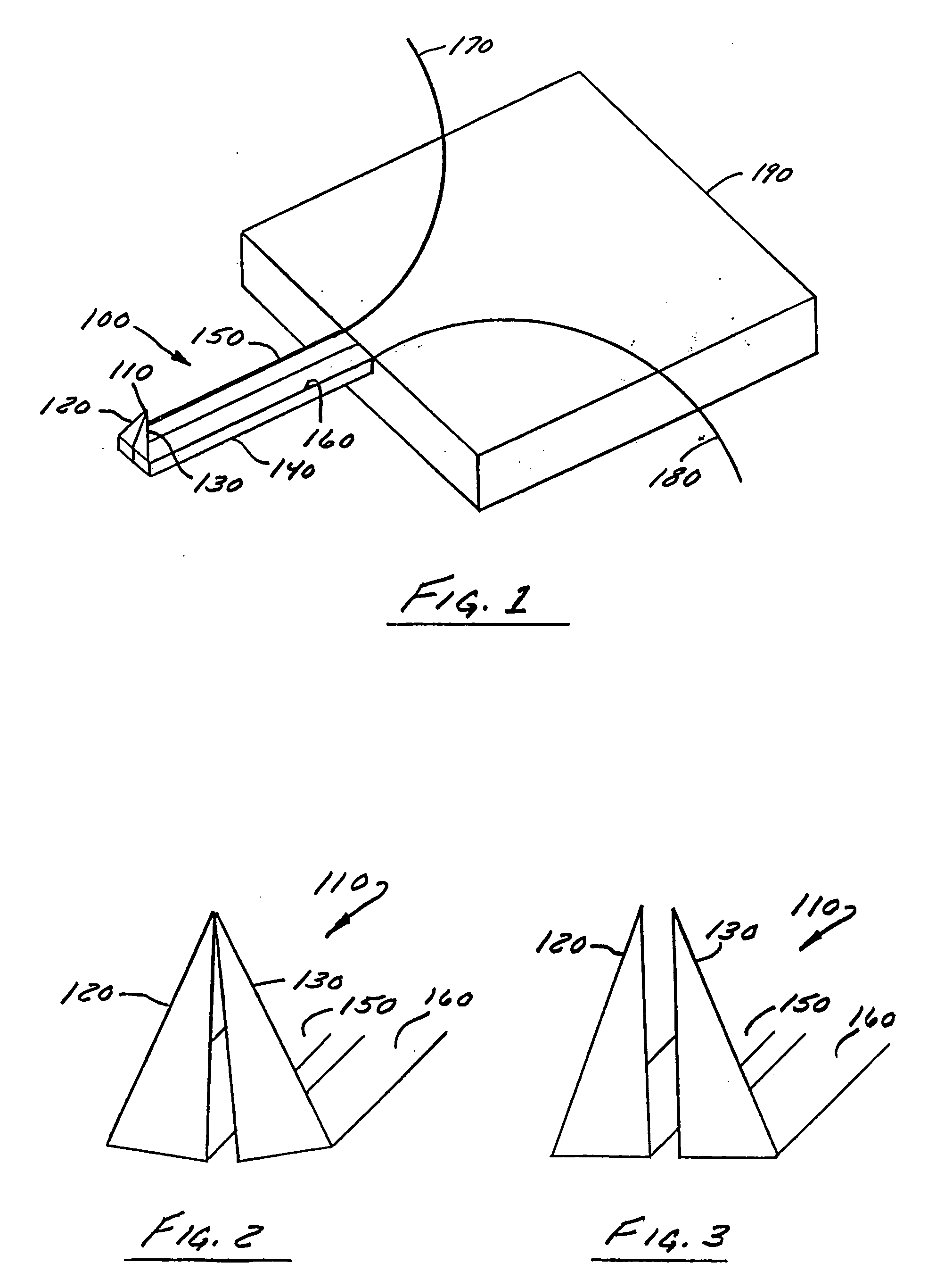
[0053]FIG. 1 is an exemplary illustration of a probe 100 particularly adapted for both imaging and manipulating samples, such as biological samples, (e.g., DNA) according to one embodiment. The probe 100 can include a cantilever 140 and a tip or tweezers 110 mounted substantially perpendicular to the cantilever 140. The tip 110 can include a first tip or prong 120 and a second tip or prong 130 mounted substantially perpendicular to the cantilever. The cantilever 140 can be mounted to a base 190 and can have a longitudinal axis running from the end of the cantilever mounted to the base to the opposite, free end of the cantilever. Preferably, the tips 120 and 130 can be mounted substantially perpendicular to the longitudinal axis of the cantilever. The cantilever 140 can include a first cantilever portion 150, and a second cantilever portion 160 disposed generally parallel thereto. A first electrode 170 and a second electrode 180 can be coupled to the tips 120 and 130 or the cantileve...


PUM

PropertyMeasurementUnit
molecular length scaleaaaaaaaaaa
thickness t2aaaaaaaaaa

Abstract

A method and apparatus for manipulating the surface of a sample including a cantilever, a first tip mounted on the cantilever, and a second tip mounted on the cantilever, the first and the second tip being configured to combine to form an imaging probe and to separate to form a manipulation probe. The first and second tips are configured to form a first position characterized in that the tips combine to form an imaging tip and the first and the second tip are configured to form a second position characterized in that the tips separate to manipulate particles on a surface of a sample. The tips can be configured to form the first position when a voltage is applied across the tips, and preferable extend downwardly from the cantilever substantially perpendicular thereto.

Description

[0001] This application is a divisional application of U.S. application Ser. No. 09 / 904,634, filed Jul. 13, 2001, titled Method and Apparatus for Manipulating a Sample, which is a continuation-in-part of U.S. application Ser. No. 09 / 855,960, filed May 15, 2001, titled Apparatus and Method for Isolating and Measuring Movement in Metrology Apparatus, which is a continuation-in-part of U.S. application Ser. No. 09 / 803,268, filed Mar. 9, 2001, each of which is incorporated by reference herein.BACKGROUND OF THE INVENTION [0002] 1. Field of Invention [0003] The present invention is directed to scanning probe microscopy. More particularly, the present invention is directed to a method and apparatus for characterizing and manipulating a sample. [0004] 2. Description of Related Art [0005] Presently, scanning probe microscopes (SPMs) are typically used to determine the surface characteristics of a sample, commonly biological or semiconductor samples, to a high degree of accuracy, down to the ...

Claims


Application Information

Patent Timeline
Patent Type & Authority Applications(United States)
IPC IPC(8): G01B5/28G01B21/30G01B11/00G01D5/26G01Q10/02G01Q10/04G01Q10/06G01Q30/20G01Q60/00G01Q70/02G01Q70/08G01Q70/16G01Q80/00G01Q90/00
CPCG01B5/28G01D5/26G01Q10/02G01Q10/04B82Y35/00G01Q70/02G01Q70/08G01Q70/16G01Q80/00G01Q10/06
Inventor CHAND, AMIKJOLLER, KEVIN J.BABCOCK, KENNETH L.HARRIS, MICHAEL K.
Owner BRUKER NANO INC
Learn More