
MEMS based micro vapor compression refrigeration system for microelectronic and photonic thermal control

a micro-vapor compression refrigeration and photonic thermal control technology, applied in the direction of cooling fluid circulation, lighting and heating apparatus, domestic cooling apparatus, etc., can solve the problems of further reduction in size, need to dissipate, and limited technology for refrigerating devices

Inactive Publication Date: 2005-07-07
SHAKESPEARE WALTER JEFFREY
View PDF0 Cites 27 Cited by
  • Summary
  • Abstract
  • Description
  • Claims
  • Application Information

AI Technical Summary

Benefits of technology

[0006] A micro-vapor compression refrigeration system on a MEMS chip is invented that maintains the temperature and optical or electrical performance of a photonic or electronic device. This micro-refrigerator operates on the standard vapor compression refrigeration cycle similar to a home refrigerator or air conditioner with choice of working fluid adapted to the application. It is envisione...

Problems solved by technology

The technology available for refrigerating the device is limited to either a thermoelectric cooler which utilizes the Peltier effect, or some type of large external refrigeration system with coolant piped to the component.
One of the most significant limitations preventing further reduction in size is the need to dissipate thermal energy2,1.
While it may be possible to further increase the active junction density by utilizing an external refrigeration system, this approach is not practical for desktop or laptop computing applications.

Method used


Image

  • MEMS based micro vapor compression refrigeration system for microelectronic and photonic thermal control
  • MEMS based micro vapor compression refrigeration system for microelectronic and photonic thermal control
  • MEMS based micro vapor compression refrigeration system for microelectronic and photonic thermal control

Examples


Embodiment Construction

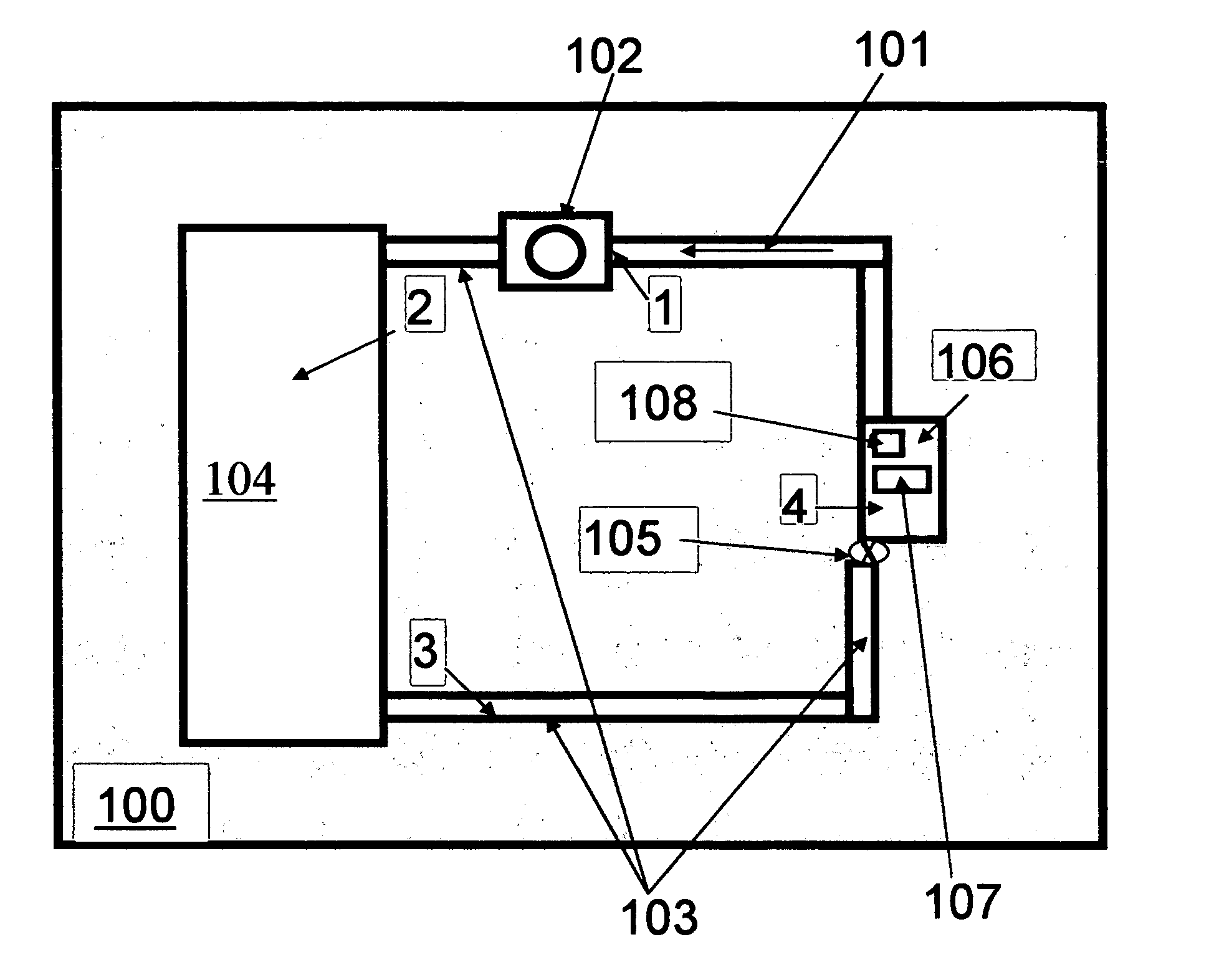
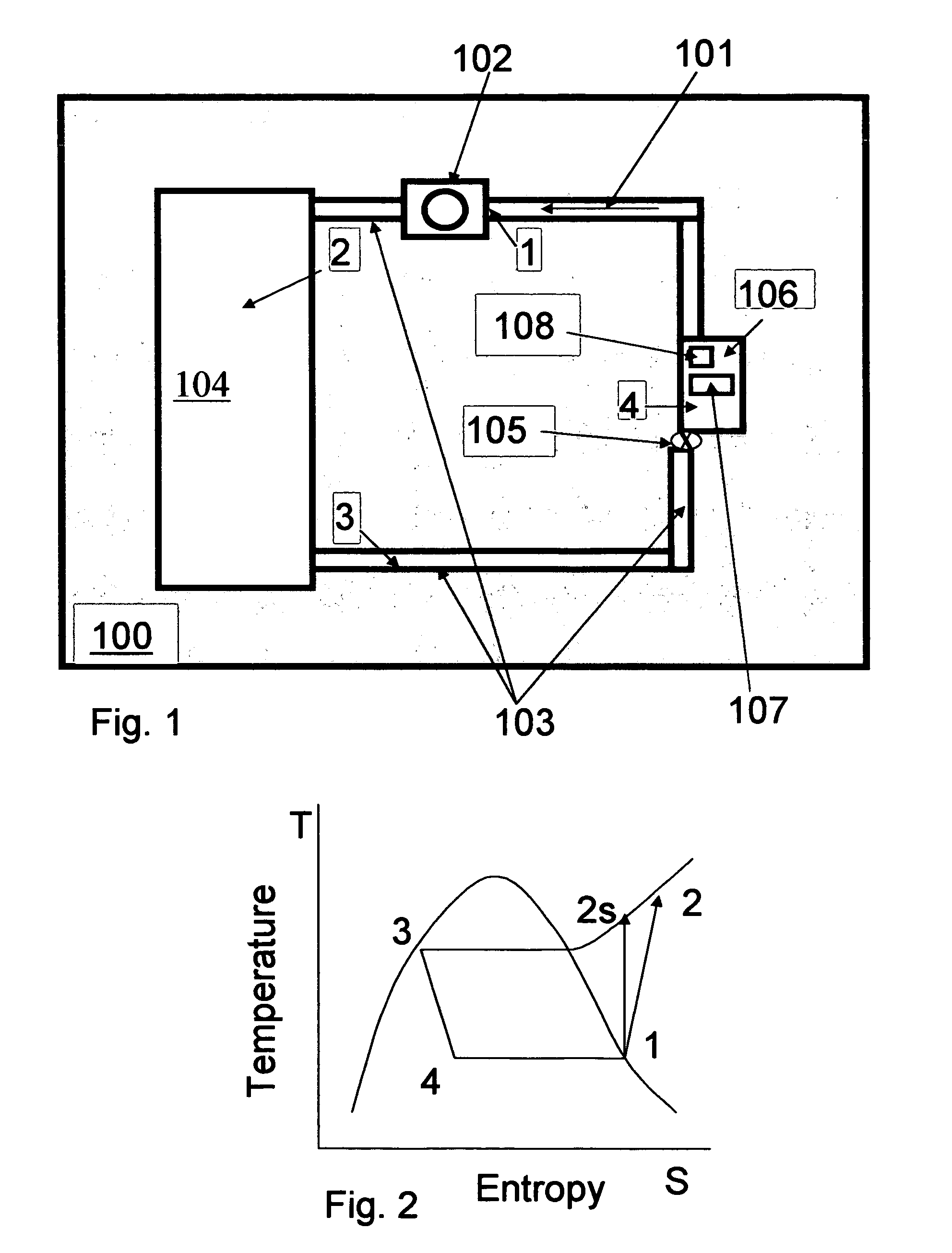
[0012]FIG. 1 shows schematically the MEMS vapor compression refrigerator on a submount 100. The refrigerant fluid 101 is compressed in the micro-compressor section 102 and piped 103 to the condenser 104 where it is condensed to a liquid at a temperature slightly above ambient. The liquid is piped 103 to a pressure reducing orifice expander 105 arranged near the evaporator cavity 106. The photonic or electronic chip 107 is mounted atop an evaporator cavity 106 that has been etched into the substrate material. Heat is conducted from the photonic or electronic chip into the evaporator cavity where it completes the evaporation of the refrigerant and is carried away by the refrigerant fluid. The warmed refrigerant is piped to the compressor section 102 and the cycle repeats. A thermal sensor 108 such as a thermistor or thermocouple measures the temperature for control purposes. The thermodynamic cycle with the corresponding states of the refrigerant is illustrated schematically in FIG. 2...


PUM


Abstract

A micro-refrigerator is fabricated using Micro-Electro Mechanical Systems processing and is used to thermally control photonic or microelectronic circuits. Temperatures below local ambient are possible due to the refrigeration capability of the device and unwanted parasitic heat such as from the walls or lid of an enclosure is minimized due to the small size of the cooled mounting area for the integrated circuit. Localized cooling is provided by jets of vapor droplet mixture controlled to impinge directly onto the hottest regions of a microelectronic or photonic integrated circuit allowing greater circuit density and thermal dissipation at isolated regions within the integrated circuit and advantageously improving performance. Methods of manufacturing micro-scale refrigerator elements including the compressor, evaporator and condenser are defined. This device is a direct improvement over the commonly used thermoelectric cooler for thermal control of microelectronic or photonic devices.

Description

FIELD OF THE INVENTION [0001] The invention pertains to the application of a Micro-Electro Mechanical Systems (MEMS) based micro vapor compression refrigeration system to thermally control electronic or photonic devices for improved performance and lower cost. BACKGROUND OF THE INVENTION [0002] Recent advances in fiber optics and photonics have resulted in a vast increase in the volume of information that can be transmitted optically. This has occurred in two fundamental ways. The speed of modulation of the optical signal has increased to upwards of 40 Gb / s and the wavelength spacing between adjacent channels is only a few tenths of a nanometer. To maintain this performance, the temperature of the photonic device must be held to within less than one degree Celsius of the design temperature1. This temperature is usually less than the ambient temperature surrounding the device requiring active refrigeration. The technology available for refrigerating the device is limited to either a ...

Claims


Application Information

Patent Timeline
IPC IPC(8): F25B13/00
CPCF25B13/00F25B2500/01F25B2400/15F25B2313/0271
Inventor SHAKESPEARE, WALTER JEFFREY
Owner SHAKESPEARE WALTER JEFFREY
Learn More