Ink jet recording apparatus

a recording apparatus and ink jet technology, applied in the direction of printing, other printing apparatus, etc., can solve the problems of increasing the production cost of the ink jet recording apparatus, the inability of each flexible flat cable to have a sufficiently great width, and the need for electric wiring to be formed at higher accuracy and difficulty, so as to prevent the temperature of each driver circuit from being excessively increased, the production cost of the wiring cable can be reduced, and the effect of convenient formation

Inactive Publication Date: 2005-06-30
BROTHER KOGYO KK
View PDF5 Cites 16 Cited by
  • Summary
  • Abstract
  • Description
  • Claims
  • Application Information

AI Technical Summary

Benefits of technology

[0011] In the ink jet recording apparatus according to the present invention, the nozzles are arranged in one or more arrays extending in the first direction, and the pressure changing devices are grouped into the two groups that are arranged in the second direction substantially perpendicular to the first direction. The two flexible wiring cables are electrically connected to the two groups of pressure changing devices, respectively, and extend from the two groups of pressure changing devices in the opposite directions, respectively, that are parallel to the second direction. Therefore, the wiring cables can have respective widths corresponding to a length or respective lengths of the array or arrays of nozzles in the first direction. Thus, even if the total number of the nozzles employed may be increased, the density of electric wires of each wiring cable need not be increased in contrast to the above-indicated conventional ink jet recording apparatus. Consequently the wiring cables can be easily formed and accordingly the production cost of the wiring cables can be re...

Problems solved by technology

Thus, each of the flexible flat cables cannot have a sufficiently great width.
This means that in each of the flexible flat cables, the ele...

Method used


Image

  • Ink jet recording apparatus
  • Ink jet recording apparatus
  • Ink jet recording apparatus

Examples


first embodiment

[0022] Hereinafter, there will be described preferred embodiments of the present invention by reference to the drawings. FIG. 1 shows an ink jet recording apparatus as the present invention. The recording apparatus includes four ink cartridges 2 (only one cartridge 2 is shown) that store respective different color inks.

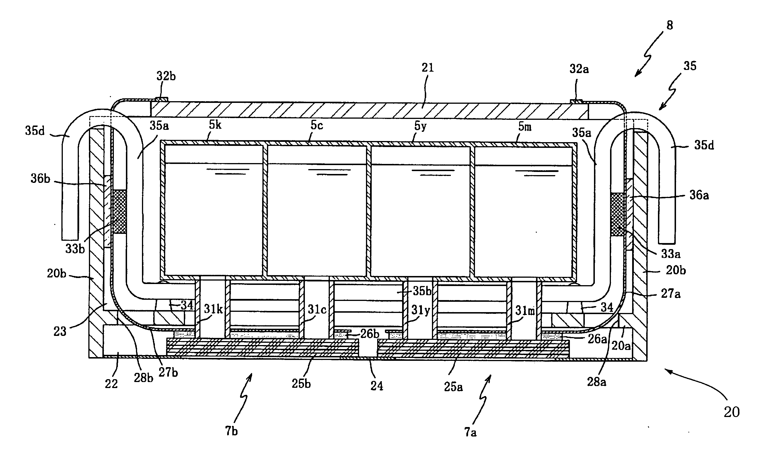
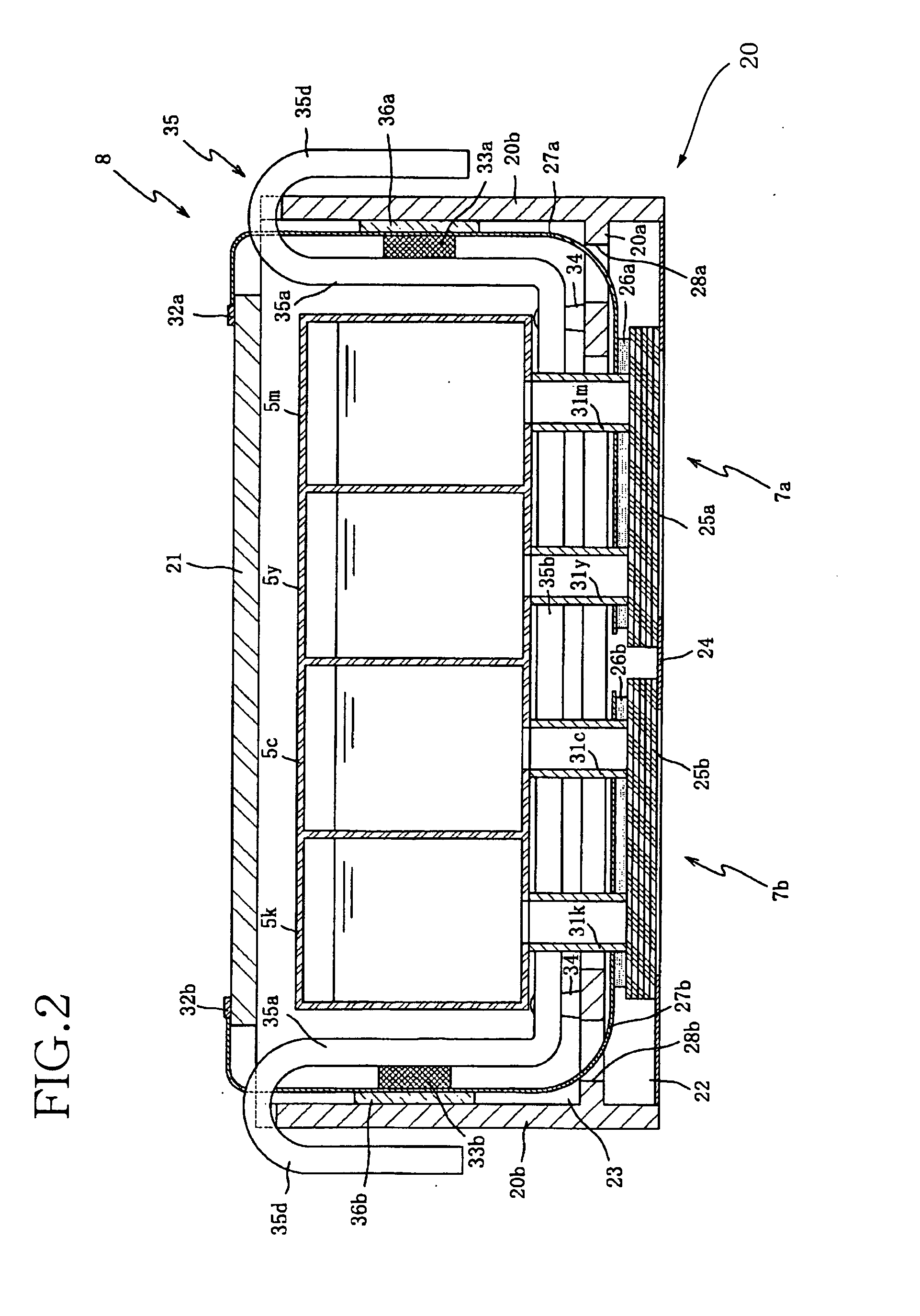
[0023] The ink jet recording apparatus includes a housing 1, indicated by broken line; an ink cartridge supporting member 3 that supports the ink cartridges 2 such that each of the cartridges 2 is attachable to, and detachable from, the supporting member 3 in directions indicated by arrow X; four ink supply tubes 4; four buffer tanks 5 that accommodate the four color inks, respectively, that are supplied from the four ink cartridges 2 via the four ink supply tubes 4, respectively; two recording heads 7 that cooperate with each other to eject respective droplets of the four color inks accommodated by the four ink tanks 5, toward a recording sheet 6 as a sort of recordi...

third embodiment

[0049]FIG. 8 shows another heat sink 235 as the present invention. The heat sink 235 may be employed by the recording head unit 8 shown in FIG. 1, in place of the heat sink 35.

[0050] The heat sink 235 includes a connection portion 235b that extends along respective rear side walls of four buffer tanks 5 (5m, 5y, 5c, 5k). Like the heat sink 35 and / or the heat sink 135, the heat sink 235 additionally includes two side walls 235a, 235a, two exposed portions 235d, 235d, two through-holes 235e, 235e, two fixation portions 235f, 235f, and four holes 235c. Since the connection portion 235b has an area substantially equal to a sum of respective areas of the respective rear side walls of the four buffer tanks 5, the heat sink 235 can enjoy an improved heat radiating property.

[0051] In each of the illustrated embodiments, the ink jet recording apparatus employs the head holder 20 including the bottom wall 20a that supports the recording heads 7, and additionally including the two side walls ...


PUM


Abstract

An ink jet recording apparatus, including nozzles each of which ejects a droplet of ink toward a recording sheet and which are arranged in one or more arrays in a first direction; pressure changing devices each of which changes a pressure of the ink to be supplied to a corresponding one of the nozzles so that the one nozzle ejects the droplet of ink, wherein the pressure changing devices are grouped into two groups arranged in a second direction perpendicular to the first direction; two flexible wiring cables which are electrically connected to the two groups of pressure changing devices, respectively, and which extend from the two groups of pressure changing devices in opposite directions, respectively, parallel to the second direction; two driver circuits which are provided on, and electrically connected to, the two wiring cables, respectively, and each of which outputs respective drive signals to drive the respective pressure changing devices of a corresponding one of the two groups; and a heat sink including two heat-conducting side walls which are opposite to each other in the second direction, a portion of each one of the two side walls contacting a corresponding one of the two driver circuits, and a heat-conducting connection portion which extends in the second direction and connects between the two side walls.

Description

[0001] The present application is based on Japanese Patent Application No. 2003-426142 filed on Dec. 24, 2003, the contents of which are incorporated herein by reference. BACKGROUND OF THE INVENTION [0002] 1. Field of the Invention [0003] The present invention relates to an ink jet recording apparatus and in particular to such an ink jet recording apparatus having a construction in which heat generated by a driver circuit that outputs a drive signal used to eject a droplet of ink is radiated by a heat sink. [0004] 2. Related Art Statement [0005] Patent Document 1 (Japanese Patent Application Publication P2002-240306 or its corresponding U.S. Pat. No. 6,679,595B2) or Patent Document 2 (Japanese Patent Application Publication P2003-080793 or its corresponding U.S. patent application Publication No. 2003-063449A1) discloses an ink jet recording apparatus including two recording heads that eject droplets of ink and cooperate with each other to record an image on a recording medium. Each...

Claims


Application Information

Patent Timeline
IPC IPC(8): B41J2/055B41J2/045B41J2/14B41J2/175
CPCB41J2/17526B41J2/14072
Inventor KUBO, TOMOYUKI
Owner BROTHER KOGYO KK
Why Eureka
Try Eureka