Eureka AIR delivers breakthrough ideas for toughest innovation challenges, trusted by R&D personnel around the world.

Plasma display and driving method thereof

a technology of plasma and driving method, which is applied in the direction of static indicating devices, address electrodes, instruments, etc., can solve the problems of bad discharge, distorted waveforms alternately applied to the x and y electrodes in the sustain period, and resistors for current restriction, etc., to prevent bad discharge

Inactive Publication Date: 2005-06-30
SAMSUNG SDI CO LTD
View PDF11 Cites 7 Cited by
  • Summary
  • Abstract
  • Description
  • Claims
  • Application Information

AI Technical Summary

Problems solved by technology

Since the DC plasma displays have electrodes exposed in the discharge space, they allow a current to flow in the discharge space while a voltage is supplied, and therefore they problematically require resistors for current restriction.
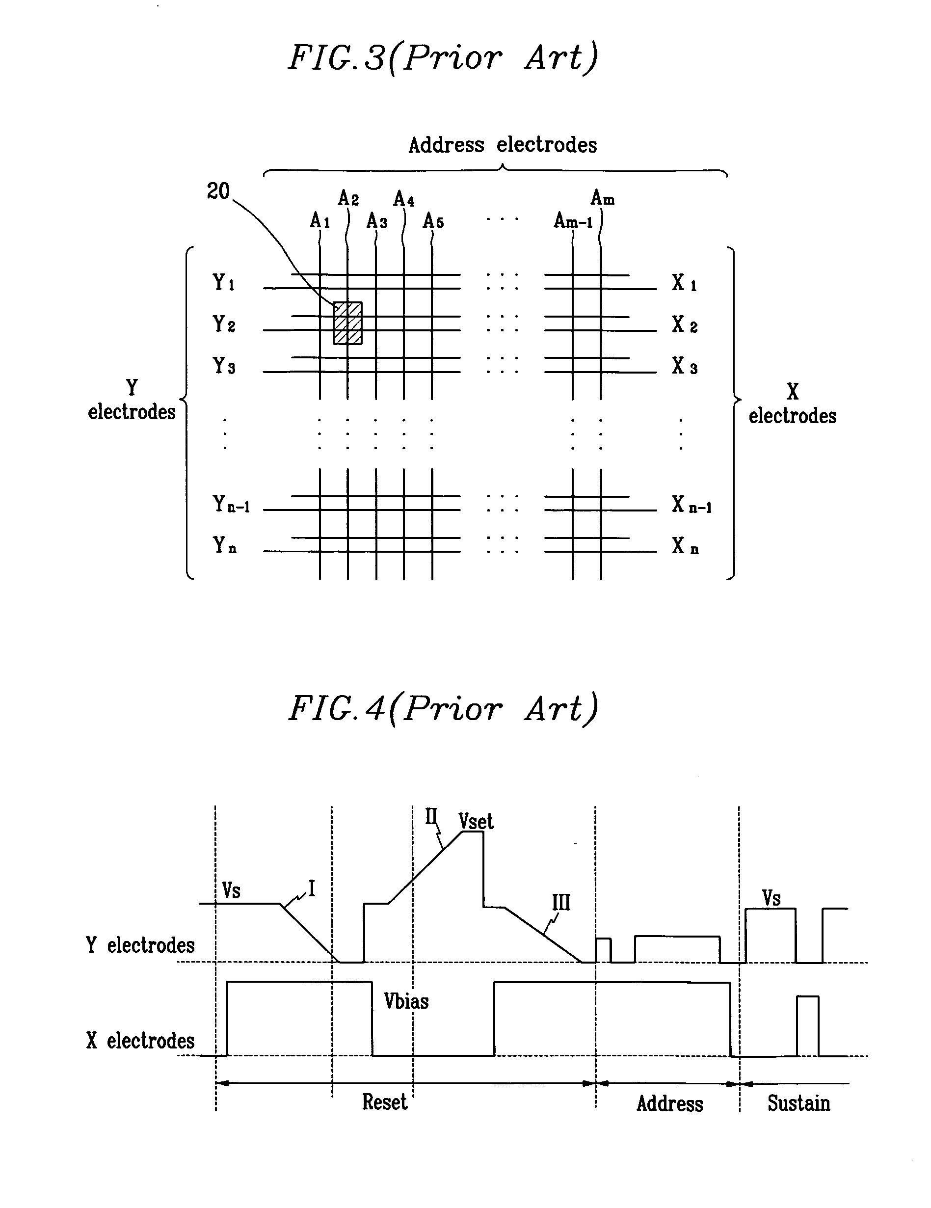
However, since insufficient priming particles are generated in the discharge cells when a first sustain pulse is applied after an address period in the conventional plasma display, bad discharge is generated.
However, since the waveform applied to the Y electrode (to which waveforms for resetting and scanning are additionally applied) during the reset period is different from the waveform applied to the X electrode in the conventional plasma display, the circuit for driving the Y electrode is different from the circuit for driving the X electrode.
Accordingly, no impedance matching on the driving circuit of the X and Y electrodes is performed, the waveforms alternately applied to the X and Y electrodes in the sustain period are distorted, and bad discharges occur.

Method used


Image

  • Plasma display and driving method thereof
  • Plasma display and driving method thereof
  • Plasma display and driving method thereof

Examples


Embodiment Construction

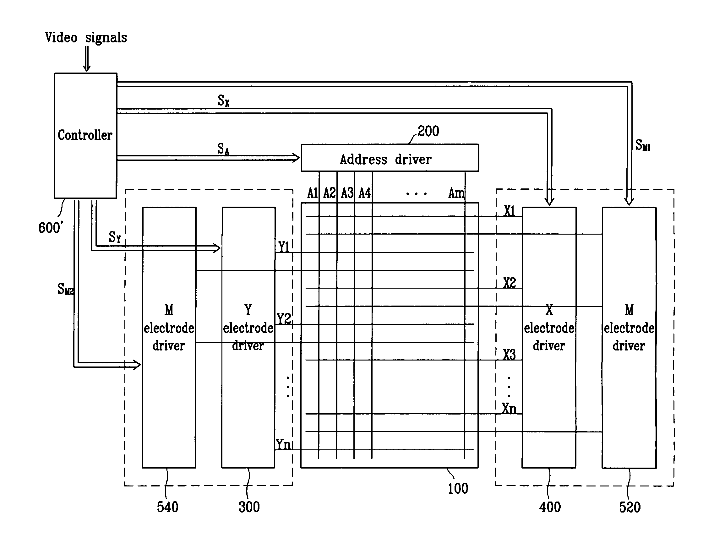
[0045]FIG. 5 shows an electrode arrangement diagram of a plasma display according to an exemplary embodiment of the present invention. Address electrodes A1 to Am are provided in parallel in a column direction, and (n / 2+1) Y electrodes Y1 to Yn / 2+1, (n / 2+1) X electrodes X1 to Xn / 2+1, and n median electrodes (referred to as M electrodes hereinafter) are provided in a row direction. That is, the M electrodes are provided between the Y and X electrodes, and the Y electrode, the X electrode, the M electrode, and the address electrode form single discharge cell 30 to thus configure a four-electrode structure.

[0046] The X and Y electrodes function as electrodes for applying sustain voltage waveforms, and the M electrodes function as electrodes for applying reset waveforms and scan pulse voltages.

[0047] Referring now to FIGS. 6 and 7A to 7E, a driving method according to the first exemplary embodiment of the present invention will now be described. Each subfield includes a reset period, ...


PUM


Abstract

A plasma display and driving method thereof. A median electrode is formed between X and Y electrodes for receiving sustain pulse voltages, and a reset waveform and a scan pulse voltage are applied to the median electrode. A short gap discharge is performed between the X electrode and the median electrode during the initial interval of a sustain interval, and a long gap discharge is performed between the X and Y electrodes during the normal sustain interval to thus perform a stable discharge. The X and Y electrode drivers are realized through comparable circuits since the waveforms applied to the X and Y electrodes are substantially symmetric.

Description

CROSS REFERENCE TO RELATED APPLICATION [0001] This application claims priority to and the benefit of Korea Patent Application No. 10-2003-0085465 filed on Nov. 28, 2003 in the Korean Intellectual Property Office, the content of which is incorporated herein by reference. BACKGROUND OF THE INVENTION [0002] (a) Field of the Invention [0003] The present invention relates to a plasma display and a driving method thereof. [0004] (b) Description of the Related Art [0005] Recently, flat panel displays, including liquid crystal displays (LCDs), field emission displays (FEDs), and plasma displays, have been actively developed. The plasma displays have better luminance and light emission efficiency as compared to the other types of flat panel devices, and also have wider view angles. Therefore, the plasma displays have come into the spotlight as substitutes for the conventional cathode ray tubes (CRTs) in large displays of greater than 40 inches. [0006] The plasma display is a flat display tha...

Claims


Application Information

Patent Timeline
Patent Type & Authority Applications(United States)
IPC IPC(8): G09G3/20G09G3/288G09G3/291G09G3/292G09G3/293G09G3/294G09G3/298H01J11/12H01J11/14H01J11/22H01J11/24H01J11/26H01J11/32H01J11/34
CPCG09G3/2927G09G3/293G09G3/294G09G2320/0228G09G2300/04G09G2310/066G09G3/2986G09G3/296
Inventor YI, JEONG-DOOKIM, JEONG-NAMKIM, TAE-WOOKIM, JOON-YEONCHAE, SU-YONG
Owner SAMSUNG SDI CO LTD
Why Eureka
Eureka Blog
Learn More