
Method and apparatus for optimal multiple beam transmit weightings for beam to beam handoff in a switched beam system

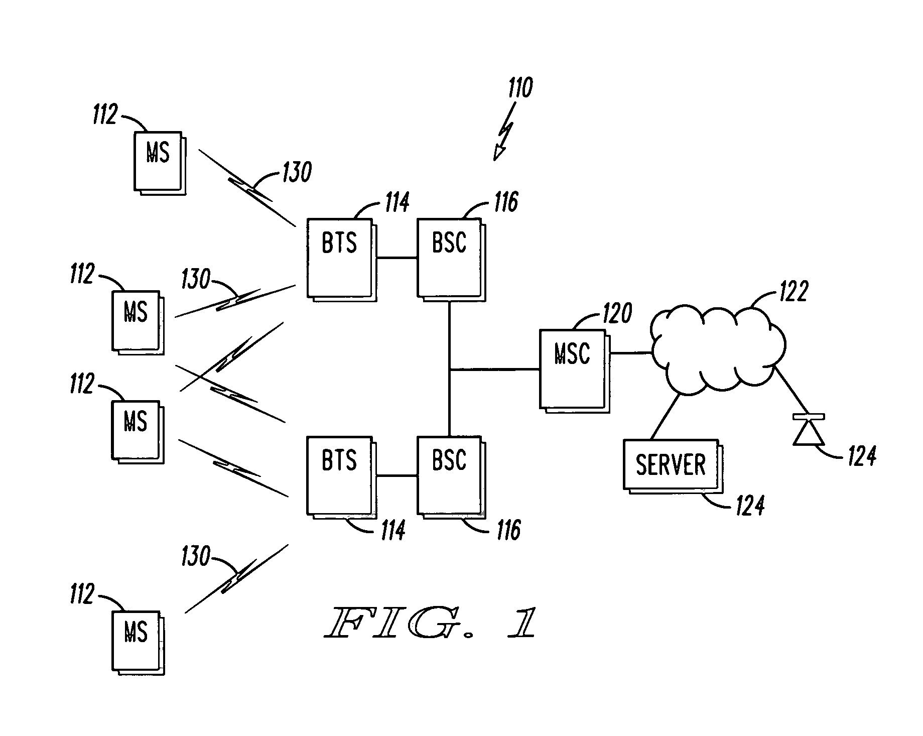
a beam-to-beam handoff and beam-to-beam technology, applied in the field of wireless communication, can solve the problems of system not providing momentary overlapping coverage, reducing the overall system capacity, and increasing the number of dropped calls

Active Publication Date: 2005-06-23
GOOGLE TECH HLDG LLC
View PDF14 Cites 36 Cited by
  • Summary
  • Abstract
  • Description
  • Claims
  • Application Information

AI Technical Summary

Problems solved by technology

Some wireless systems may employ hard handoff between beams (that is, the system does not provide any momentary overlapping coverage utilizing two or more beams).
Hard handoffs are not desirable, however, as they may result in increased dropped calls and may reduce the overall system capacity relative to other handoff methods CDMA supports softer-handoffs between sectors, in which multiple sectors transmit to the mobile simultaneously, but softer-handoff relies on assistance from the mobile in the form of pilot signal strength measurements.
Since the beams share a common pilot signal, pilot measurements from the mobile cannot distinguish between the beams, and thus the mobile cannot assist the base station in the selection of the transmit beams.
Generally, with only a common pilot, the mobile does not know which beams within the sector are transmitting to the mobile and the mobile cannot separate and identify the signals from the different beams.
However, problems with previous systems limit the effectiveness of the transfers and inhibit some implementations.
Further, previous systems can be expensive to implement because of the problems these systems must attempt to overcome.
These systems often drop calls, have limited functionality, have reduced and / or limited system capacity and typically require additional circuitry.
These limitations reduce the systems overall effectiveness and frustrate customers.

Method used


Image

  • Method and apparatus for optimal multiple beam transmit weightings for beam to beam handoff in a switched beam system
  • Method and apparatus for optimal multiple beam transmit weightings for beam to beam handoff in a switched beam system
  • Method and apparatus for optimal multiple beam transmit weightings for beam to beam handoff in a switched beam system

Examples


Embodiment Construction

[0021] These various embodiments provide for methods, systems and equipment or apparatuses that can be used to maximize system capacity, minimize transmit power requirements, optimize a received signal-to-noise ratio (SNR), and provide better optimized handoffs between beams. The present embodiments provide for the optimization of wireless beam synthesis by attempting to optimize and / or maximize the SNR that would be seen at the mobile. These embodiments measure reverse link signals to determine and generate a weighting that can be applied to one or more antennas in transmitting forward link signals. The weighting allows for enhanced handoff between beams. The better optimized transmit power further enhances the capacity of a wireless communication system and reduces interference at other non-intended wireless devices.

[0022] The present embodiments provide for a better optimized maintenance of wireless connections between a base station and wireless mobile devices or other sensitiv...


PUM


Abstract

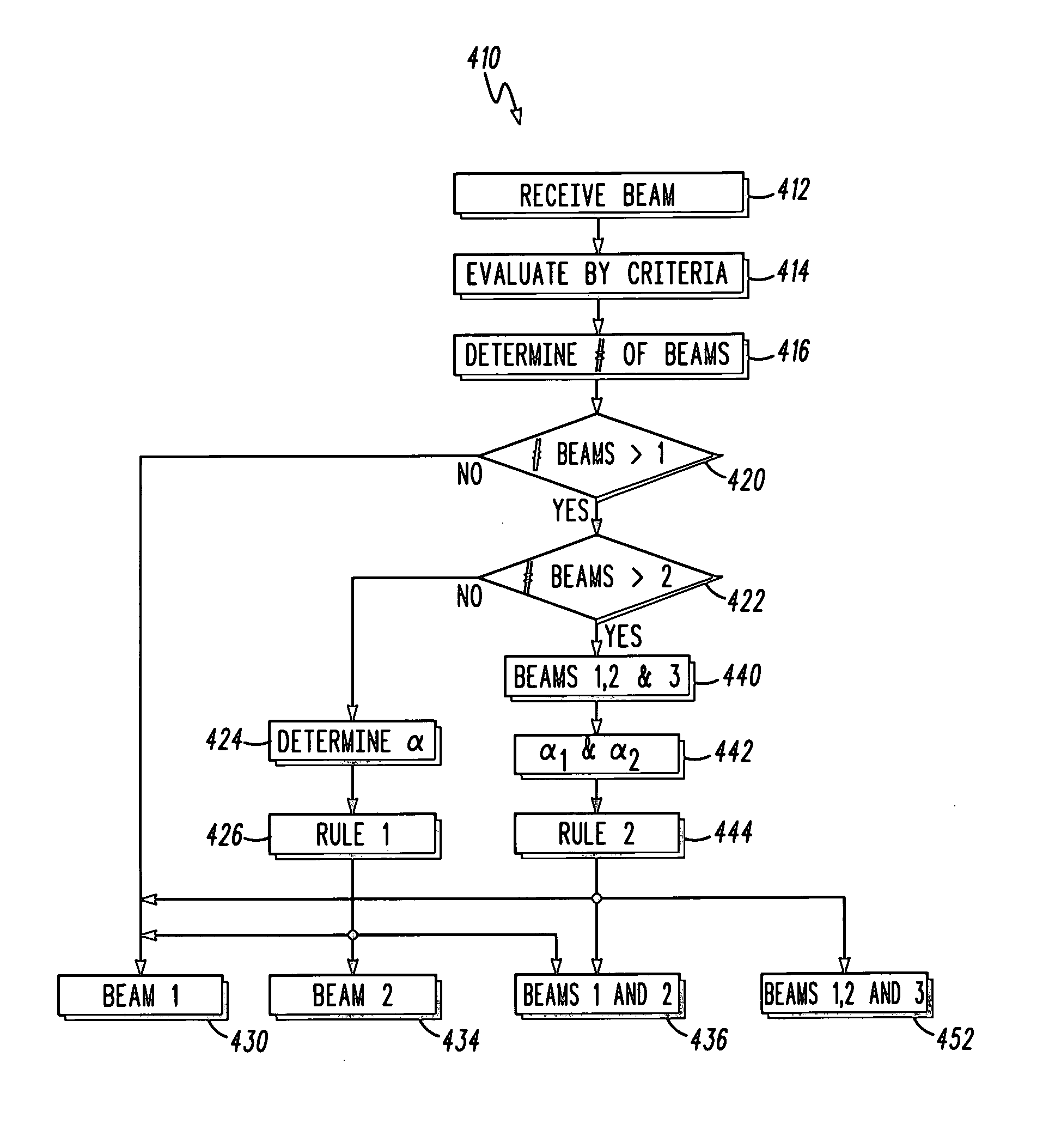
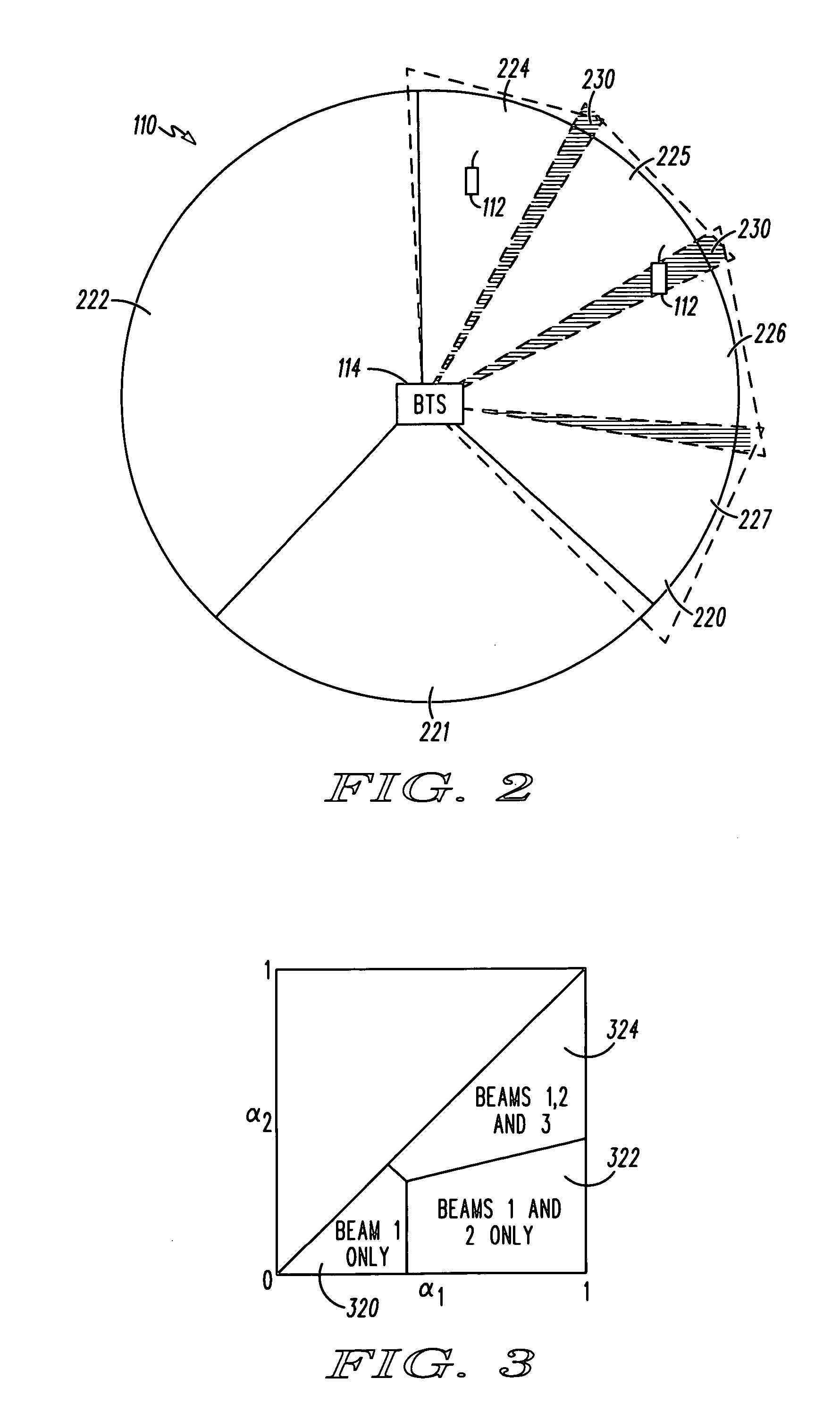
A method, apparatus and system are provided for use in better optimizing switched beam, wireless communications. In some embodiments, a method is provided that receives a communication over a first wireless reverse link beam, selects a type of beam weighting control, determines a rule according to the type of beam weighting control, and determining a weighting of a forward link beam according to the rule. The method can further determine an energy of the first reverse link beam, and determine a first gain energy ratio based on the first reverse link beam energy, such that the weighting is determined by applying the first gain energy ratio to the rule. Some embodiments further determine a pilot beam configuration, wherein the rule is determined according to the pilot beam configuration and the selected type of beam weighting control.

Description

FIELD OF THE INVENTION [0001] The present invention relates generally to wireless communication, and more particularly to the better optimization of transmitting wireless communications over a wireless system. BACKGROUND OF THE INVENTION [0002] In a switched beam system, the wireless communication beams are fixed. As such, wireless mobile devices must be handed off from one beam to the next as the mobile travels around a base station. Some wireless systems may employ hard handoff between beams (that is, the system does not provide any momentary overlapping coverage utilizing two or more beams). Hard handoffs are not desirable, however, as they may result in increased dropped calls and may reduce the overall system capacity relative to other handoff methods CDMA supports softer-handoffs between sectors, in which multiple sectors transmit to the mobile simultaneously, but softer-handoff relies on assistance from the mobile in the form of pilot signal strength measurements. Since the b...

Claims


Application Information

Patent Timeline
IPC IPC(8): H04B7/06H04W16/24H04W36/06H04W36/08
CPCH04B7/0408H04B7/0634H04W36/08H04W36/06H04W16/24H04W36/085
Inventor FRANK, COLINLUZ, YUDA Y.TENBROOK, KEITH A.
Owner GOOGLE TECH HLDG LLC
Learn More