Relative position information correction device, relative position information correction method, relative osition information correction program, shape vector generation device, shape vector generation method, and shape vector generation program

a relative position information and correction device technology, applied in the direction of process and machine control, navigation instruments, instruments, etc., can solve the problems of inability to obtain the method of preparing a digital map database is not uniform, and the decoder cannot achieve the desired result using map matching, etc., to achieve the effect of reducing the distance between an event occurrence point and a feature node, reducing the error included in the relative location representing the event occurrence point, and reducing the distance

Inactive Publication Date: 2005-06-16
PANASONIC CORP
View PDF0 Cites 22 Cited by
  • Summary
  • Abstract
  • Description
  • Claims
  • Application Information

AI Technical Summary

Benefits of technology

[0109] Further, the shape data generation apparatus of the invention selects a point that is located within a predetermined distance, along a shape data, from a node or a feature node designated at a starting point or an end point for the shape data that satisfies a predetermined condition, and designates the selected point as a first feature node. Then, the shape data generation apparatus selects a point that is located within a predetermined distance inward, along the shape data, of an n-th (n is a natural number) feature node that satisfies the predetermined condition, and designates the selected point as an (n+1)-th feature node. Therefore, when map matching is performed for a shape data representing a curved

Problems solved by technology

However, the method for preparing a digital map database is not uniform, and differs slightly, depending on the company, and accordingly, the setup of a node differs slightly in accord with the skill of an operator.
Therefore, the same problem occurs as was previously described, i.e., either the event occurrence point is shifted on a display or can not be displayed.
However, when a digital map database employed by an encoder differs from a digital map database employed by a decoder, and when a shape data is extended, a problem arises in that a location shift occurs when

Method used


Image

  • Relative position information correction device, relative position information correction method, relative osition information correction program, shape vector generation device, shape vector generation method, and shape vector generation program
  • Relative position information correction device, relative position information correction method, relative osition information correction program, shape vector generation device, shape vector generation method, and shape vector generation program
  • Relative position information correction device, relative position information correction method, relative osition information correction program, shape vector generation device, shape vector generation method, and shape vector generation program

Examples


first embodiment

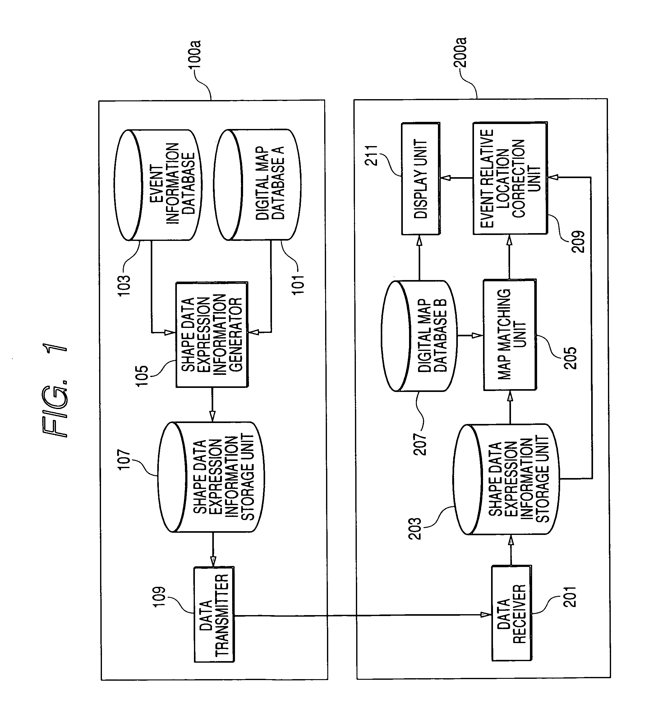
[0153]FIG. 1 is a block diagram showing a car navigation system comprising a relative location data correction apparatus according to a first embodiment of the present invention. As is shown in FIG. 1, the relative location data correction apparatus of this embodiment comprises a transmission apparatus 100a and a reception apparatus 200a. The transmission apparatus 100a includes: a digital map database 101, which corresponds to the first map database in claim 1; an event information database 103; a shape data expression information generator 105, which corresponds to the location expression information conversion means and the first total length determination means; a shape data expression information storage unit 107; and a data transmitter 109. The reception apparatus 200a includes: a data receiver 201; a shape data expression information storage unit 203; a map matching unit 205; a digital map database 207, which corresponds to the second map database; an event relative location ...

second embodiment

[0180]FIG. 5 is a block diagram showing a car navigation system comprising a relative location data correction apparatus according to a second embodiment of the present invention. In FIG. 5, the same reference numerals are provided for portions overlapping those in FIG. 1 (first embodiment), and no explanation for them will be given. As is shown in FIG. 5, the relative location data correction apparatus for the second embodiment comprises a transmission apparatus 100b and a reception apparatus 200b.

[0181] In addition to the components of the transmission apparatus 100a in the first embodiment, the transmission apparatus 100b in this embodiment includes: a shape data compression / transformation processor 151, which corresponds to the shape data compression / transformation means in the claims; a compressed shape data expression information storage unit 153; a compressed shape data decoder 155, which corresponds to the first shape data decoding means; and an event relative location corr...

third embodiment

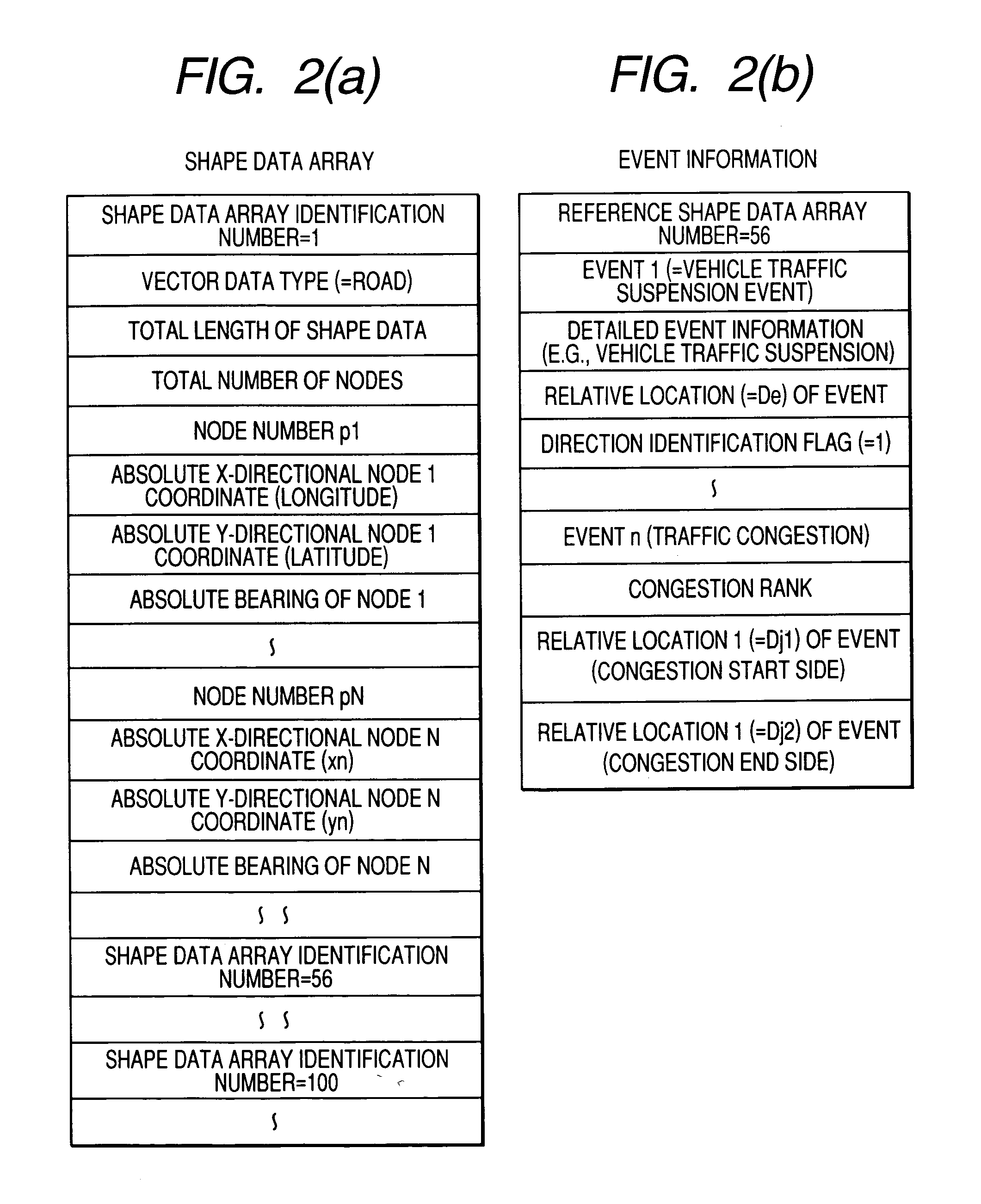
[0196] The configuration of a car navigation system comprising a relative location data correction apparatus according to a third embodiment is the same as that for the second embodiment. However, in this embodiment, when a shape data expression information generator 105 converts an event occurrence point into a relative location De in a shape data, the event occurrence point is represented as a relative location viewed from a feature point (hereinafter referred to as a “feature node”), such as an intersection curved at a specific angle and located between the base point node at the starting point and a relative node at the terminal end. For example, the event occurrence point is represented as a point some hundreds of meters from the feature node. In FIG. 8(b) is shown an example data structure for event information converted by the shape data expression information generator 105. The example data structure for the shape data in FIG. 8(a) is the same as is that in FIG. 6(a) for the...


PUM


Abstract

The objective of the present invention is to provide a relative location data correction apparatus, a relative location data correction method and a relative location data correction program that can cope with the shifting of a relative location between different digital map databases, and can accurately display a desired point.
The relative location data correction apparatus of the invention includes: a transmission apparatus (100a), for transmitting to a reception apparatus (200a) event information, such as that for a traffic accident or traffic congestion, that is prepared based on a digital map database (101); and the reception apparatus (200a), for employing the event information received from the transmission apparatus (100a) to display an event occurrence point on a map provided by a digital map database (207), and for correcting the location of the event occurrence point before being displayed. The transmission apparatus (100) calculates the total length of a road section, and transmits, to the reception apparatus (200a), shape data expression information that includes the total length. The reception apparatus (200a) calculates the total length of the road section, and employs the two total lengths to correct the relative location of the event occurrence point.

Description

TECHNICAL FIELD [0001] The present invention relates to a relative location data correction apparatus, a relative location data correction method and a relative location data correction program for absorbing a relative location difference between different digital map databases and for accurately displaying a desired point. The present invention also relates to a shape data generation apparatus, a shape data generation method and a shape data generation program for setting a feature node for a shape data that is to be generated, based on map data stored in a digital map database, to indicate a predetermined road section. BACKGROUND ART [0002] A car navigation system used, for example, for vehicles has a function that employs a digital map database and location data, obtained based on information received by a GPS receiver, to display on a screen a map of the periphery of a driver's vehicle, or to display, together with a map, a traveling locus and the results of a search made for a ...

Claims


Application Information

Patent Timeline
IPC IPC(8): G01C21/26G01C21/30G08G1/09G08G1/0967
CPCG01C21/26G01C21/30G08G1/096775G08G1/096716G08G1/096758G08G1/092G06T7/40G08G1/0969
Inventor ADACHI, SHINYA
Owner PANASONIC CORP
Why Eureka
Try Eureka