Electrode structure

a technology of conductive paste and electrode, applied in the field of electrode structure, can solve the problems of low productivity, increase in manufacturing cost and molding cracking, and the electrode produced using such a conductive paste does not follow, and achieves the effect of simple structure and simple manner

Inactive Publication Date: 2005-06-16
MORI KENJI +8
View PDF3 Cites 21 Cited by
  • Summary
  • Abstract
  • Description
  • Claims
  • Application Information

AI Technical Summary

Benefits of technology

[0012] That is, it is an object of the present invention to provide an electrode structure capable of efficiently using (letting react) a material that can be a non-polarized electrode component such as a conductive paste, allowing the material to fully demonstrate the effect as the non-polarized electrode and maintaining the performance as the non-polarized electrode. To achieve this object, the following points (1) to (3) are particularly taken into consideration:
[0013] (1) Enabling energization for a long period without increasing the amount of components that can be non-polarized electrodes.
[0014] (2) Preventing loss of performance as non-polarized electrodes, that is, preventing any change in pH.
[0015] (3) Providing an electrode with a simple structure that can be manufactured using a simple method and used in a simple manner.

Problems solved by technology

However, the problem is that the electrode produced using such a conductive paste does not follow Faraday's law and it is only approximately {fraction (1 / 2)} to {fraction (1 / 10)} of the amount of electricity calculated from Faraday's law and the content of the electrode that can be energized.
For this reason, the paste component grows in thickness, causing problems like an increase in the manufacturing cost and cracking during molding.
However, these examples have problems in which since the electrode is divided into a plurality of small electrodes its productivity is low, and in which since a plurality of terminals penetrates an insulating base the plurality of terminals need to be connected during energization.

Method used


Image

  • Electrode structure
  • Electrode structure
  • Electrode structure

Examples


example 1

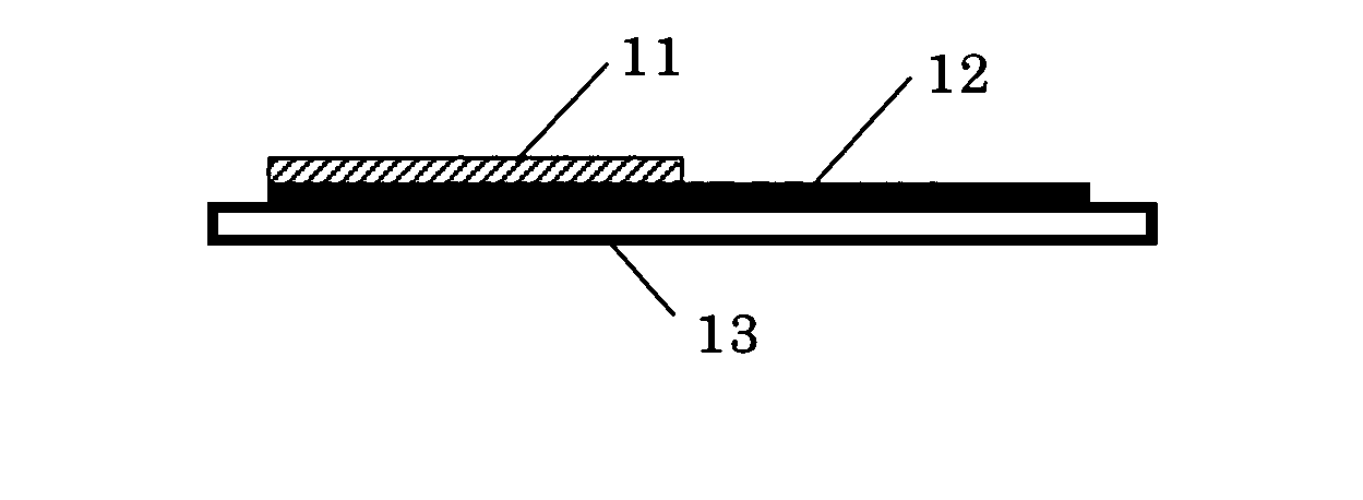
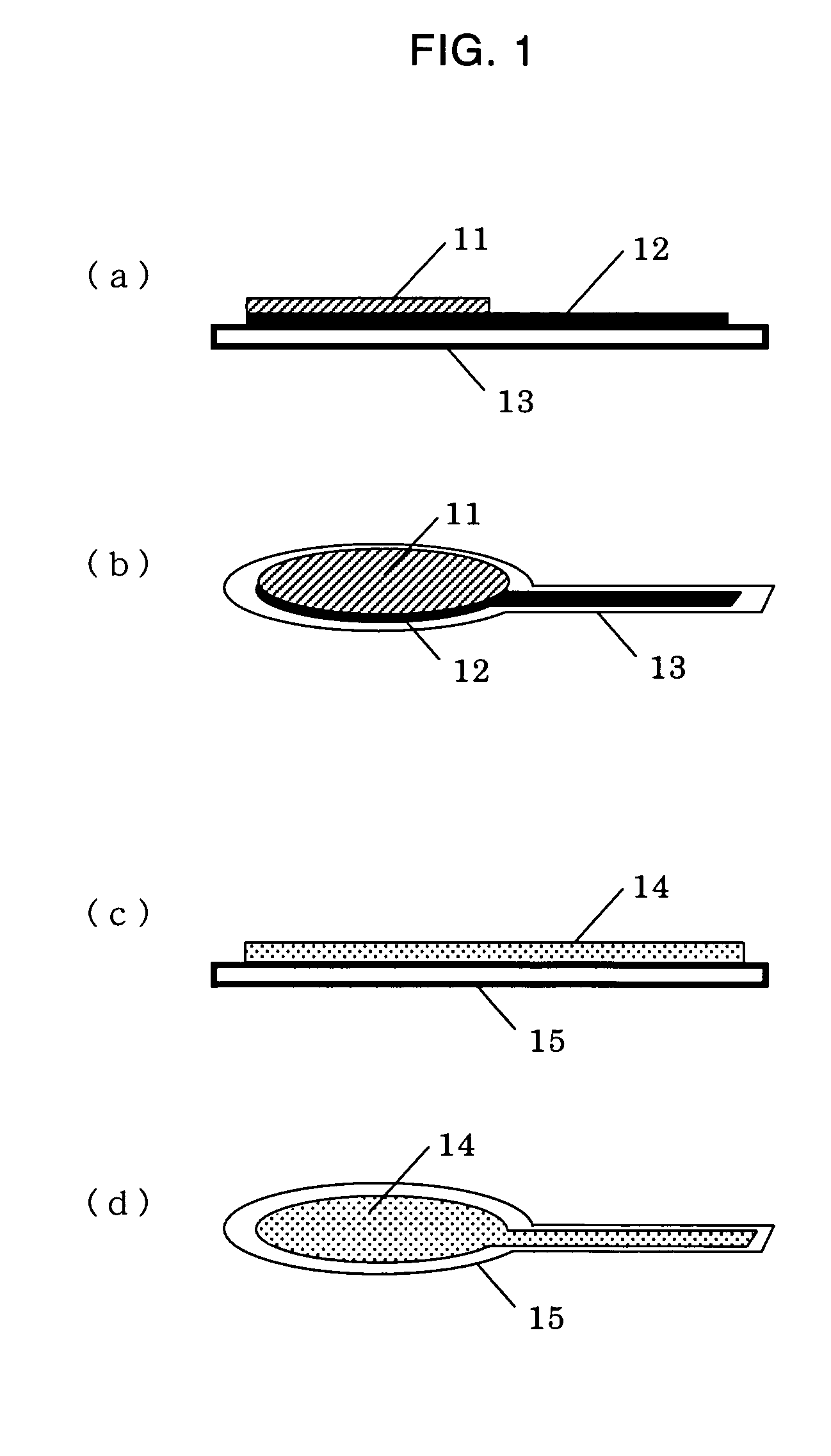
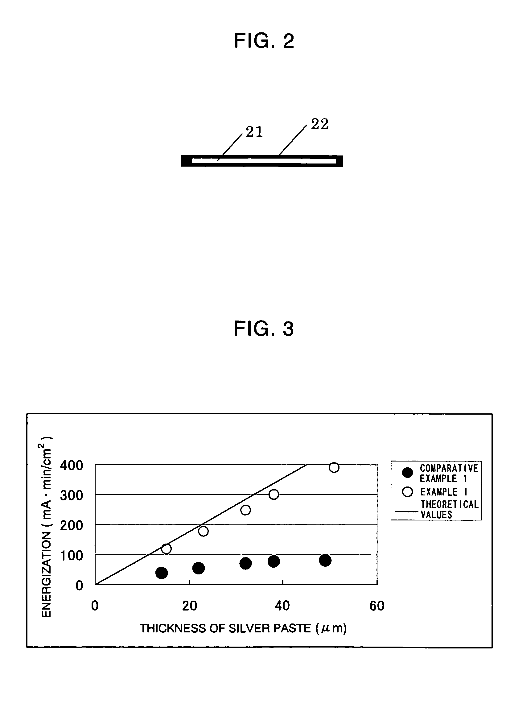
[0042] Production of electrode of the present invention: A polyethylene terephthalate film was used as the insulating base 13 and a conductive paste predominantly made of carbon was applied onto this film to 10 μm in thickness (first layer 12). Furthermore, a conductive paste predominantly made of silver was applied onto the carbon to several types of thickness (second layer 11). The thickness of the silver paste after drying was 15, 23, 32, 38 and 51 μm, respectively.

[0043] Production of reference electrode: Two silver plates containing silver of purity greater than 99.99% were prepared, used as an anode and cathode, and energized in a physiological salt solution at 1 mA / cm2 for six hours. At this time, the reacting electrode (silver / silver chloride electrode) on the anode side was used as a reference electrode.

[0044] Measurement of amount of energization: The electrode of the present invention was used as an anode and the reference electrode was used as a cathode, these electrod...


PUM

PropertyMeasurementUnit
areaaaaaaaaaaa
thicknessaaaaaaaaaa
thicknessaaaaaaaaaa

Abstract

An electrode structure is provided which is capable of efficiently using a material that can be a non-polarized electrode component, allowing the material to fully demonstrate the effect as the non-polarized electrode and maintaining the performance. This electrode structure comprises an insulating base (13), a polarized component layer (first layer) (12) laminated on the insulating base so as not to penetrate the insulating base, the polarized component layer comprising a conductive paste or metallic foil which is predominantly made of a component that can be a polarized electrode, and a non-polarized component layer (second layer) (11) provided on the polarized component layer, the non-polarized component layer comprising a conductive paste which is predominantly made of a component that can be a non-polarized electrode.

Description

TECHNICAL FIELD [0001] The present invention relates to an electrode structure applicable to a living body used in medical fields such as medical treatment and diagnostics. More specifically, the present invention relates to an apparatus for delivering physiologically active substances into the living body using electric energy and an electrode structure used for an apparatus for extracting diagnostic substances from the living body to the outside. BACKGROUND ART [0002] Iontophoresis (Acta Dermatol venereol, Vol. 64, p 93, 1984) and electroporation (Japanese Patent Publication No. 3-502416, Proc. Natl. Acad. Sci. USA, Vol. 90, pp 10504 to 10508, 1993) are methods for delivering physiologically active substances from skin and mucous membranes to the interior of the living body using electric energy. [0003] Furthermore, a method for extracting diagnostic substances from the living body and observing pathological conditions using the same principle as iontophoresis is also used (Nature...

Claims


Application Information

Patent Timeline
Patent Type & Authority Applications(United States)
IPC IPC(8): A61N1/04A61N1/30
CPCA61N1/0412A61N1/0496A61N1/0492A61N1/0428
Inventor MORI, KENJIMAEDA, HIROYUKINISHI, YOSHIHIROARIMOTO, TETSUYAHIGO, NARUHITOSATO, SHUJIOGAWA, TATSUYATAKAHASHI, SAORIFUCHITA, YASUSHI
Owner MORI KENJI
Why Eureka
Try Eureka