Fast scanner with rotatable mirror and image processing system

Inactive Publication Date: 2005-06-16
RUILING OPTICS
View PDF22 Cites 66 Cited by
  • Summary
  • Abstract
  • Description
  • Claims
  • Application Information

AI Technical Summary

Benefits of technology

[0027] The at least one light source, the at least one rotatable mirror and the at least one image sensor are arranged such that the first direction and the fourth direction define a first angle, (180°−β), and the second direction and the third direction define a second angle, (180°+β), where β has a value in the range of −15° to 15°, and when rotated, the at least one rotatable mirror causes the second direction of the light to change such that the light sequentially scans consecutive partial images of

Problems solved by technology

Although these paper documents are good candidates for electronic storage, because they vary significantly in sizes and shapes, often folded and stapled in some way, there is a lack of efficient means for scanning these documents into a computer system due to the speed limitation.
Factors limiting the scan speed of the flatbed devices are, among other things, the moving speed of the scan head, line scan rate of optical sensor, data transferring speed, and image processing speed.
The speed bottleneck for the flatbed devices is the slow moving scan head.
More specifically, it is not that the stepping motor cannot drive the scan head fast enough, it is the back and forth movement of the scan head and the start-stop action that limit the moving speed of the scan head.
Therefore, despite orders of magnitude increase in microprocessor speed and memory density in recent years, the increase in flatbed scan speed of the flatbed scanners has been incremental.
However, video camera employing area sensors usually do not have enough resolutions to replace an ordinary office scanner.
Similar to the glass-top scanning devices, the flashing light emitting out of the scan area during scanning may discomfort and harm users and the device has limited scan area while the height of the device is high, due to the need for keeping sufficient distance between the to be scanned document and the area sensor.
However, using line scan cameras for document scanning is inconvenient, for example, the document to be scanned usually needs to be faced up.
In addition, the line scan camera devices require strong scan lighting, which is uncomfortable for human eyes during frequent image capturing.
But there are issues to be resolved before rotary mirror scanners become a popular product for routine use.
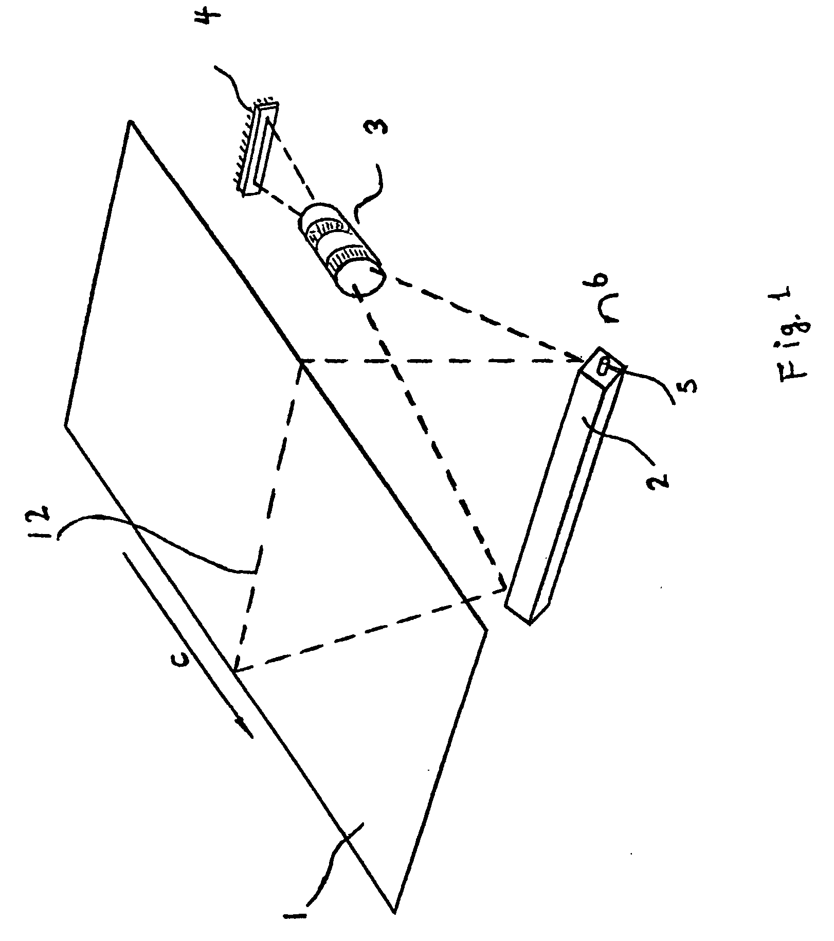
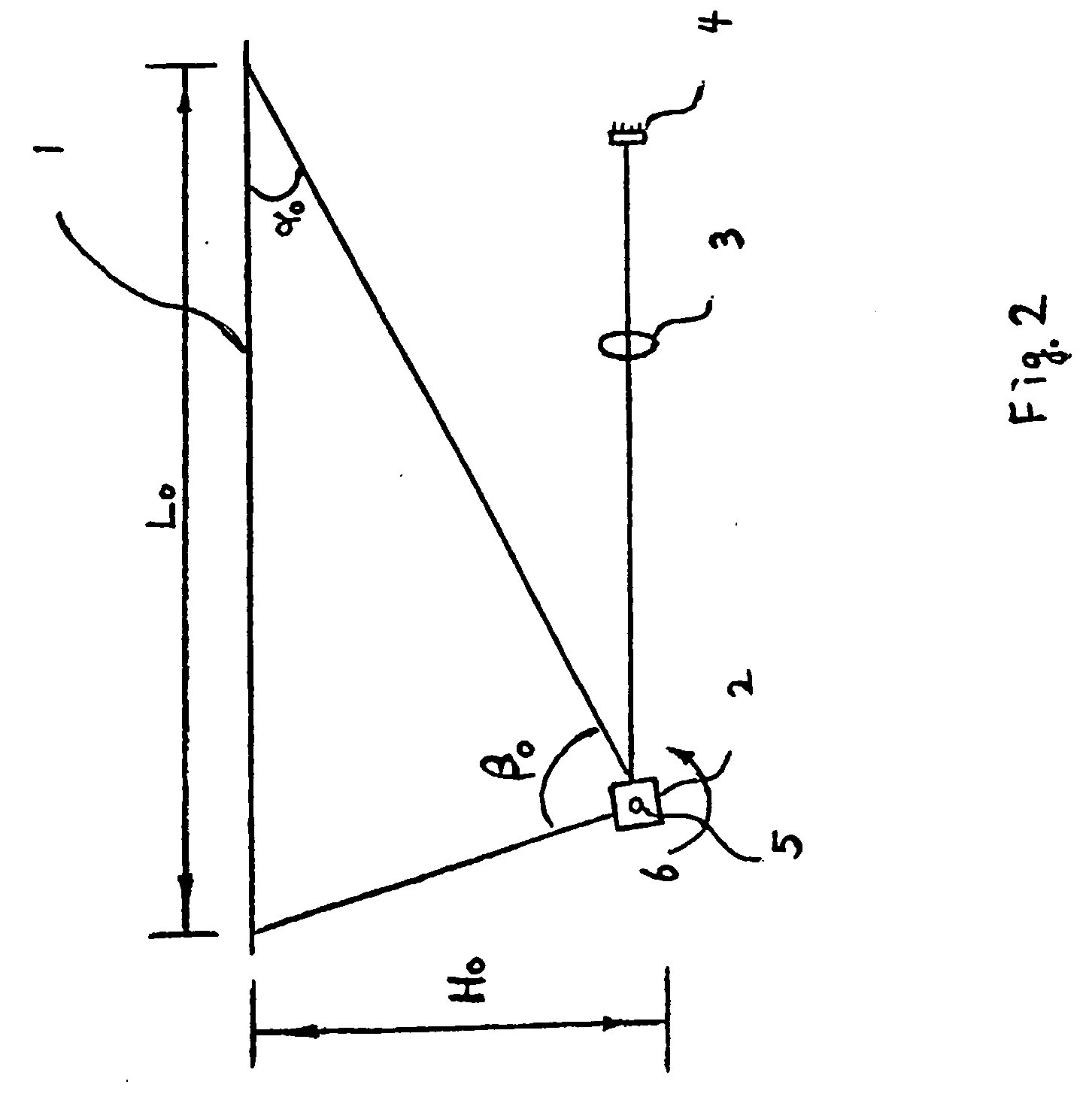
One critic issue is that a certain distance is required between line sensors and the scan area. FIGS. 1 and 2 show a scanner utilizing a line sensor and a rotary mirror.
However, this type of scanner has bulky construction and several other problems.
However, the shortening of the distance achieved by using different lenses is limited and further complicated by side effects of increasing distortion of image captured.
This design has several problems.
Image capturing device such as a digital camera employing pricy area sensors that generally do not have sufficient resolution to replace the ordinary office scanners.
The design also requires the document be placed facing up and camera facing down, occupies a relatively large space, is therefore not as convenient as flatbed scanners for frequent scanning.
The proposed method to combine the two partial images is based on the captured images, which are unreliable in achieving a high-quality combined image.
The image processing, however, is quite complex and the quality of alignments of partial images varies from scan to scan.
As a result, the approach does not provide means for quickly and reliably combining partial images into one.
Another issue in designing rotary mirror scanner is to accurately time the coordination between image processing and angular position of the rotary mirror.
However, timing main scanning cycles is difficult to implement if multiple partial images of the same original document need to be taken before they are combined into one complete image.
Additionally, cycle counting errors may be accumulated.
This method has the obvious drawback that extra components are needed.
The third method of using an optical path length finder is also not desirable for the same reason.
The third issue in the design of a rotary mirror scanner is the correction of uneven shading of the image caused by uneven lighting exposure.
However, in rotary mirror scanner design, the shading unevenness across the scan area would be greater than that in normal flatbed scanners.
The fourth issue in the design of an image scanner is the elimination of distortions in the raw image initially taken by sensors.
Still another issue is the strong light emitting out of the scan area during scanning.
This can be very uncomfortable for the eyes of a human operator.
No solution so far has been provided to implement the second method.
Therefore, a heretofore unaddressed need exists in the art to address the aforementioned deficiencies and inadequacies.

Method used


Image

  • Fast scanner with rotatable mirror and image processing system
  • Fast scanner with rotatable mirror and image processing system
  • Fast scanner with rotatable mirror and image processing system

Examples


Embodiment Construction

[0072] The present invention is more particularly described in the following examples that are intended as illustrative only since numerous modifications and variations therein will be apparent to those skilled in the art. Various embodiments of the invention are now described in detail. Referring to the drawings, like numbers indicate like components throughout the views. As used in the description herein and throughout the claims that follow, the meaning of “a”, “an”, and “the” includes plural reference unless the context clearly dictates otherwise. Also, as used in the description herein and throughout the claims that follow, the meaning of “in” includes “in” and “on” unless the context clearly dictates otherwise.

[0073] The description will be made as to the embodiments of the present invention in conjunction with the accompanying drawings 3-35. In accordance with the purposes of this invention, as embodied and broadly described herein, this invention, in one aspect, relates to ...


PUM


Abstract

A scanner for obtaining an image of an object placed on an at least partially transparent platform, wherein the platform is defined by edge portions and has at least including a first scan area and a second scan area. In one embodiment, the scanner includes a white area formed at least partially around the edge portions of the platform with a plurality of markers, optical means for sequentially scanning consecutive partial images of the object from the first scan area and the second scan area, respectively, wherein each of the consecutive partial images include an image of at least one of the plurality of markers, and an image processing system for using the image of the at least one of the plurality of markers in each of the consecutive partial images as a reference to combine the consecutive partial images so as to form a substantially complete image of the object corresponding to a full scan of the first scan area and the second scan area.

Description

CROSS-REFERENCE TO RELATED PATENT APPLICATION [0001] This application claims the benefit, pursuant to 35 U.S.C. §119(e), of provisional U.S. Patent Application Ser. Nos. 60 / 510,185, 60 / 531,249, and 60 / 572,639, filed on Oct. 10, 2003, Dec. 19, 2003 and May 19, 2004, respectively, entitled “FAST SCANNER WITH ROTARY MIRROR AND IMAGE PROCESSING SYSTEM,” by Yuping Yang, which are incorporated herein by reference in their entireties. [0002] Some references, which may include patents, patent applications and various publications, are cited in a reference list and discussed in the description of this invention. The citation and / or discussion of such references is provided merely to clarify the description of the present invention and is not an admission that any such reference is “prior art” to the invention described herein. All references cited and discussed in this specification are incorporated herein by reference in their entireties and to the same extent as if each reference was indiv...

Claims


Application Information

Patent Timeline
IPC IPC(8): F21V8/00G02B6/00G02B6/42G02B26/08H04N1/10H04N1/195H04N5/225
CPCG02B6/0016G02B6/005G02B6/0051G02B6/4298H04N2201/0081H04N1/10H04N1/195H04N1/19584H04N1/19589G02B2006/0098
Inventor YANG, YUPING
Owner RUILING OPTICS
Why Eureka
Try Eureka