
Coal and syngas fueled power generation systems featuring zero atmospheric emissions

a technology of power generation system and atmospheric emission, which is applied in the direction of liquefaction, machines/engines, lighting and heating apparatus, etc., can solve the problems of moderate increase in plant capital costs of gasification and gas cleanup, and achieve the effect of high efficiency and no atmospheric emissions

Inactive Publication Date: 2005-06-16
ANDERSON ROGER E +2
View PDF99 Cites 72 Cited by
  • Summary
  • Abstract
  • Description
  • Claims
  • Application Information

AI Technical Summary

Benefits of technology

[0005] Accordingly, a primary object of the present invention is to provide a power generation system which combusts a syngas produced from gasification of coal, biomass, or other fuel sources with oxygen to produce combustion products including carbon dioxide and water and to generate power without atmospheric emissions.
[0007] Another object of the present invention is to generate power from combustion of a hydrocarbon fuel with high efficiency and without any atmospheric emissions.

Problems solved by technology

Pollution from coal-fired power plants is a pressing environmental problem and the emission of carbon dioxide is of increasing concern in regard to global warming.
Although gasification and gas cleanup moderately increase plant capital costs, this technology is well established and currently is practiced on a large scale.

Method used


Image

  • Coal and syngas fueled power generation systems featuring zero atmospheric emissions
  • Coal and syngas fueled power generation systems featuring zero atmospheric emissions
  • Coal and syngas fueled power generation systems featuring zero atmospheric emissions

Examples


Embodiment Construction

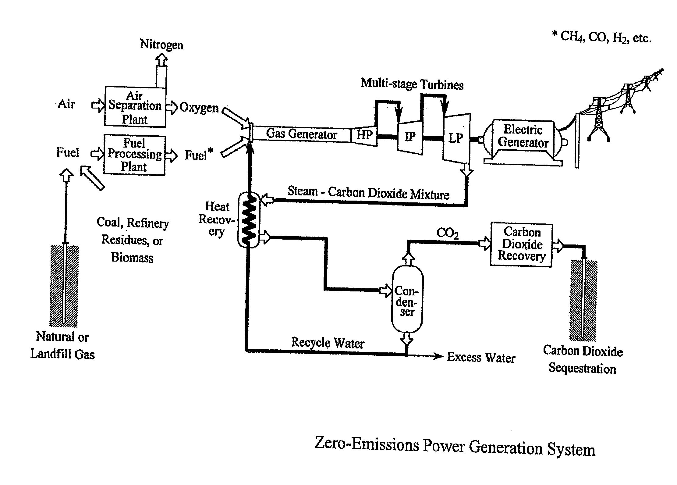
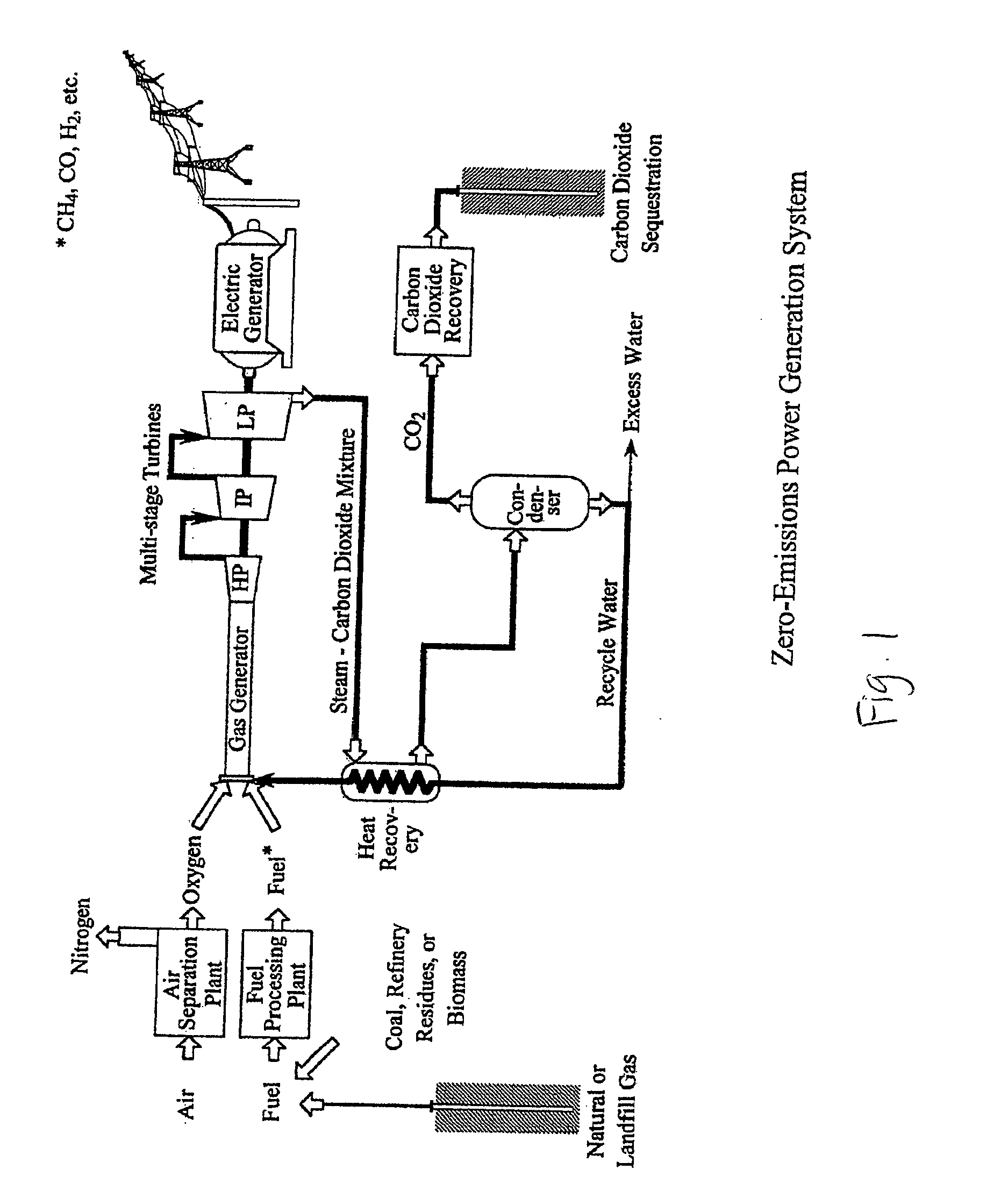
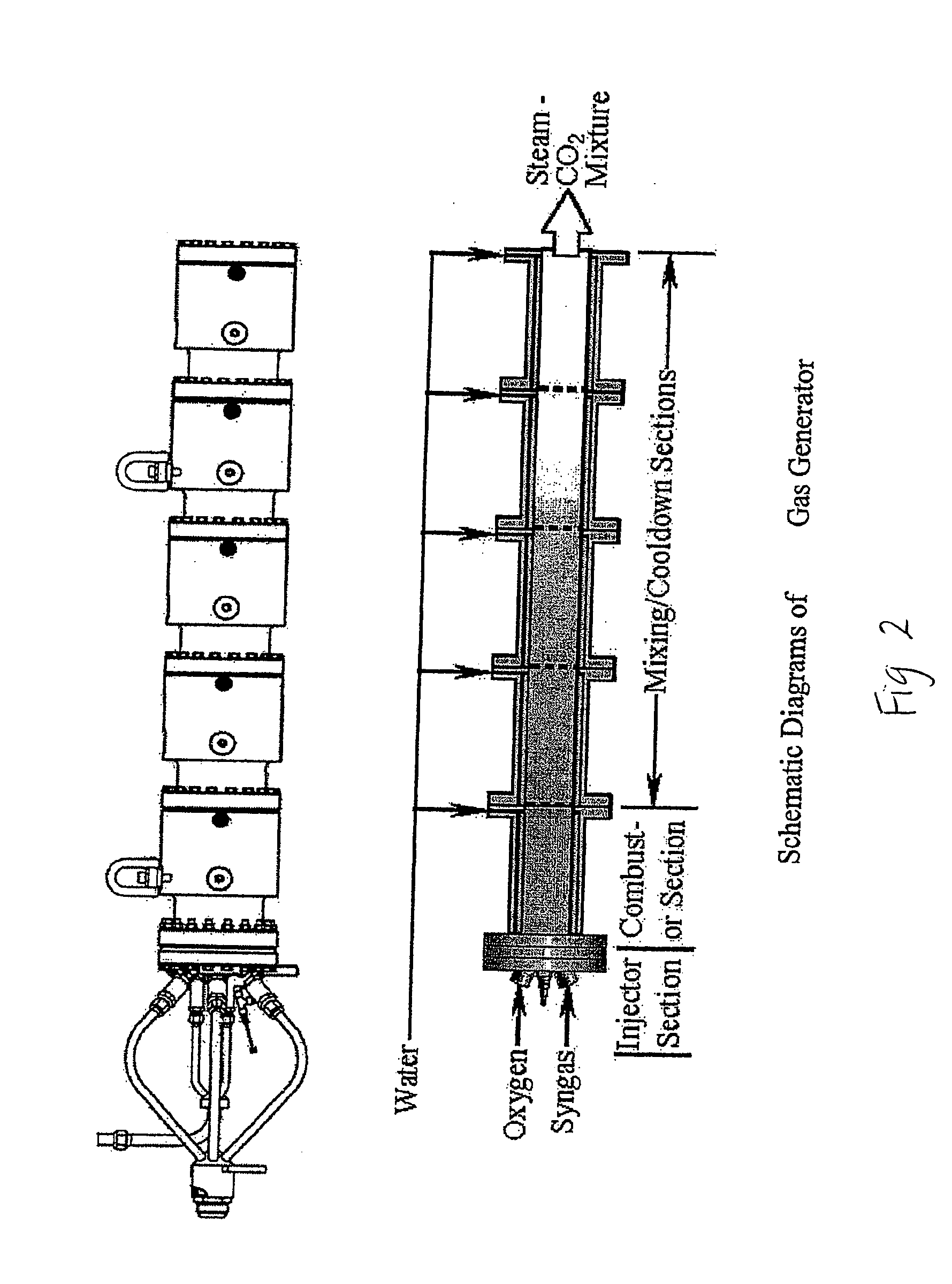
[0021] A simplified schematic diagram of the basic process of the various embodiments of this invention is shown in FIG. 1. The use of coal in this system requires the conversion of coal to syngas by means of established oxygen-blown gasification and syngas cleanup processes. Oxygen is obtained from air in an air separation plant. The syngas, oxygen and water from the plant are delivered to a gas generator where combustion takes place. The syngas is combusted with oxygen in a gas generator while water is injected into the gas generator to control the temperature of the combustion products. The mixture of combustion products and cooling water form the drive gas for the turbines. This mixture, consists primarily of steam (H2O) and carbon dioxide (CO2). The combustion products of the gas generator preferably drive (i.e. are expanded into) multiple turbines, including a high-pressure turbine (HP), typically followed by an intermediate-pressure turbine (IP) and a low-pressure turbine (LP...


PUM


Abstract

A coal syngas or other syngas fired power plant is provided with no atmospheric emissions. Coal or other starter fuel is gasified within a gasifier which also receives oxygen and steam therein. The oxygen is provided from an air separator. Syngas produced within the gasifier is combusted within a gas generator along with oxygen from the air separator. Water is also introduced into the gas generator to control the temperature of combustion of the syngas with the oxygen. Products of combustion including steam and carbon dioxide are produced within the gas generator. The combustion products are expanded through a turbine for power output and then separated, such as within a condenser. Water discharged from the condenser is at least partially recirculated back to the gasifier and the gas generator. Carbon dioxide from the separator is compressed for capture without release into the atmosphere.

Description

CROSS-REFERENCE TO RELATED APPLICATIONS [0001] This application is a divisional of U.S. patent application Ser. No. 10 / 304,290, filed on Nov. 25, 2002. This application claims benefit under Title 35, United States Code §119(e) of U.S. Provisional Application Nos. 60 / 336,648, 60 / 336,649, 60 / 336,653 and 60 / 336,673 filed on Dec. 3, 2001. This application also incorporates by reference the entire contents of U.S. Pat. Nos. 5,709,077, 6,206,684, 6,247,316, 6,637,183 and U.S. patent application Ser. No. 10 / 155,932, having a filing date of May 24, 2002. BACKGROUND OF THE INVENTION [0002] Currently and for the near future, coal provides a substantial portion of the world's supply of electric energy. Pollution from coal-fired power plants is a pressing environmental problem and the emission of carbon dioxide is of increasing concern in regard to global warming. [0003] Coal is a desirable fuel for electric power generation especially if power plants are designed to give zero atmospheric emiss...

Claims


Application Information

Patent Timeline
IPC IPC(8): F01K23/06F02C3/22F02C3/28F02C3/30
CPCF01K23/068Y02E20/18F02C3/28F02C3/30F23L2900/07001F25J3/04018F25J3/04121F25J3/04496F25J3/04533F25J3/04545F25J2260/80Y02C10/14Y02E20/322Y02E50/12Y02E50/346Y02E20/185Y02E20/16F02C3/22Y02C20/40Y02E20/32Y02E20/34Y02E50/10Y02E50/30
Inventor ANDERSON, ROGER E.BRANDT, HARRYVITERI, FERMIN
Owner ANDERSON ROGER E
Learn More