
Variable ratio drive system

a technology of variable ratio and drive system, which is applied in the direction of electric propulsion mounting, transportation and packaging, gearing, etc., can solve the problems of high cost of either solution, difficult installation of combination of conventional differential and large capacity power source within the available packaging space, and inability to efficiently control the full range of torque and speed requirements of wheel driven vehicles

Active Publication Date: 2005-06-09
ARVINMERITOR TECH
View PDF2 Cites 24 Cited by
  • Summary
  • Abstract
  • Description
  • Claims
  • Application Information

AI Technical Summary

Benefits of technology

[0009] The subject system provides a variable drive system that utilizes a series of drive motors in combination with a single planetary gear set that drives a differential assembly. The subject invention eliminates the need for a large capacity variable speed motor and / or a complex transmission system. Further, the subject drive system is easily incorporated into existing drive axle designs. These and other features of the present invention can be best understood from the following specification and drawings, the following of which is a brief description.

Problems solved by technology

Electric drive motor systems for a vehicle drive axle assembly typically do not have the capability to efficiently control the complete range of torque and speed requirements of a wheel driven vehicle.
Either of these solutions is expensive.
A further disadvantage is that this large capacity power source has to use a conventional axle gear differential to transfer the torque to the driving wheels on the axle assembly, and the combination of the conventional differential and large capacity power source is difficult to install within the available packaging space.
This configuration eliminates the need for a conventional differential, however, the use of a motor and drive gears for each powered wheel significantly increases system costs.

Method used


Image

  • Variable ratio drive system
  • Variable ratio drive system
  • Variable ratio drive system

Examples


Embodiment Construction

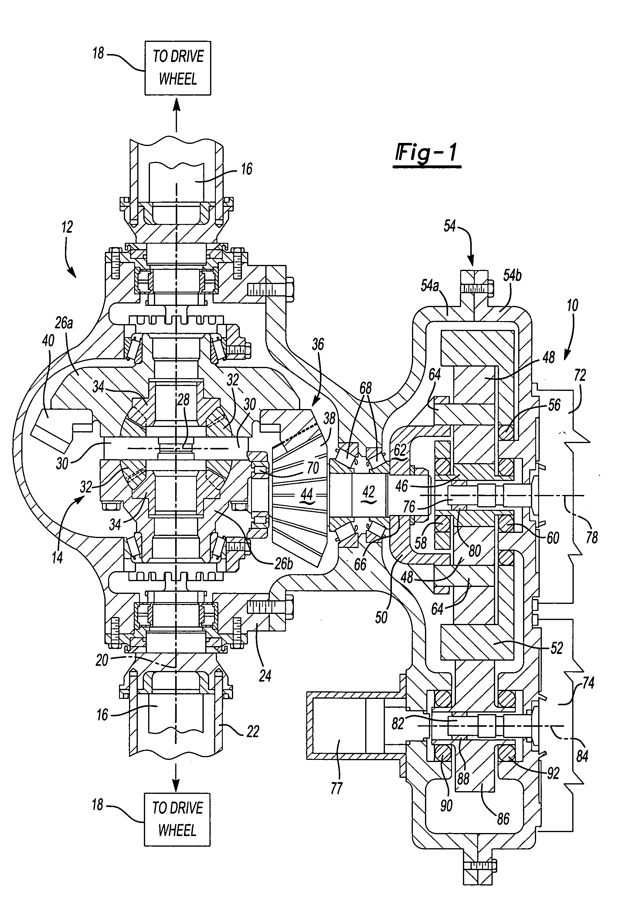
[0012] A variable ratio drive system is generally shown at 10 in FIG. 1. The drive system 10 powers a drive axle assembly 12 for a vehicle (not shown). The drive axle assembly 12 includes a center differential 14 that is operably coupled to first and second axle shafts 16. The axle shafts 16 drive a pair of laterally spaced vehicle wheels 18 about a lateral axis of rotation 20. The axle shafts 16 are substantially enclosed within an axle housing 22. The differential 14 is substantially enclosed within a carrier housing 24 that is formed as part of the axle housing 22, or bolted to or otherwise attached to the axle housing 22.

[0013] The differential 14 includes first and second differential case halves 26a, 26b that are bolted together. The first and second case halves 26a, 26b support a differential spider 28. The differential spider 28 is shaped like a cross, i.e. the differential spider has four (4) leg portions 30 (only two (2) are shown). Each leg portion 30 supports a differen...


PUM


Abstract

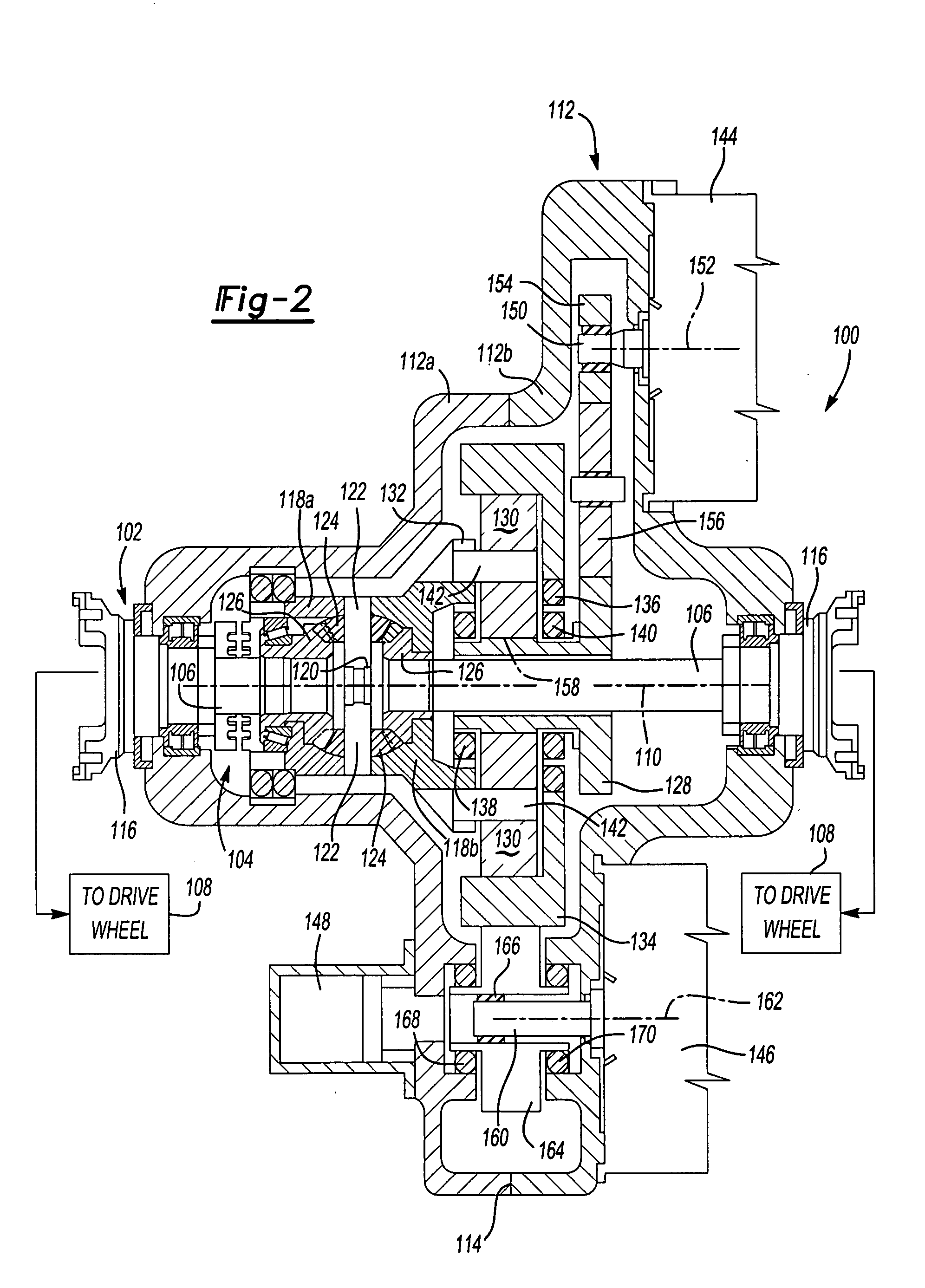
A drive system for a vehicle utilizes a series of drive motors and a single planetary gear box to provide driving input to a differential for an axle assembly. The differential drives a pair of axle shafts that drive a pair of laterally spaced wheels. The planetary gear box includes a sun gear, a plurality of planet gears in meshing engagement with the sun gear, a planet carrier that supports the planet gears, and a ring gear that is in meshing engagement with the planet gears. One drive motor drives the sun gear and another drive motor drives the ring gear. The planet carrier provides the output driving force from the planetary gear box to the differential. The motor that drives the sun gear provides for high output torque by taking advantage of a high gear ratio reduction and the motor that drives the ring gear provides for high output speed by taking advantage of a low gear ratio reduction. When both motors are simultaneously powered, a variable gear ratio is provided.

Description

BACKGROUND OF THE INVENTION [0001] The subject invention relates to a variable ratio drive system for a vehicle that utilizes a series of drive motors in combination with a single planetary gear box to provide driving input to an axle differential. [0002] Electric drive motor systems for a vehicle drive axle assembly typically do not have the capability to efficiently control the complete range of torque and speed requirements of a wheel driven vehicle. Heavy duty vehicles, such as trucks and buses for example, require a wide range of torque and speeds to accommodate the often strenuous and diverse duty cycles to which these types of vehicles are subjected. Traditionally, in order to accommodate these torque and speed range requirements, either a complex transmission is required or a large capacity variable speed electric motor must be used as a power source. Either of these solutions is expensive. A further disadvantage is that this large capacity power source has to use a conventi...

Claims


Application Information

Patent Timeline
IPC IPC(8): B60K1/02B60K6/00B60K7/00F16H3/72
CPCB60K1/02B60K2001/001F16H2048/426F16H48/08F16H3/724
Inventor GADY, RICHARDBOOTHBY, TIMOTHY
Owner ARVINMERITOR TECH
Learn More