
Reciprocating compressor driven by a linear motor

Inactive Publication Date: 2005-06-09
EMPRESA BRASILEIRA DE COMPRESSORES SA (EMBRACO)
View PDF5 Cites 85 Cited by
  • Summary
  • Abstract
  • Description
  • Claims
  • Application Information

AI Technical Summary

Benefits of technology

[0007] Thus, it is an object of the present invention to provide a reciprocating compressor driven by a linear motor, which with a simple construction and with a minimum of components with relative movement, minimizes the lateral forces on the piston, the effects of the concentration of compressive forces on the actuating means, and the consequent momenta on both the actuating means and the piston. SUMMARY OF THE INVENTION
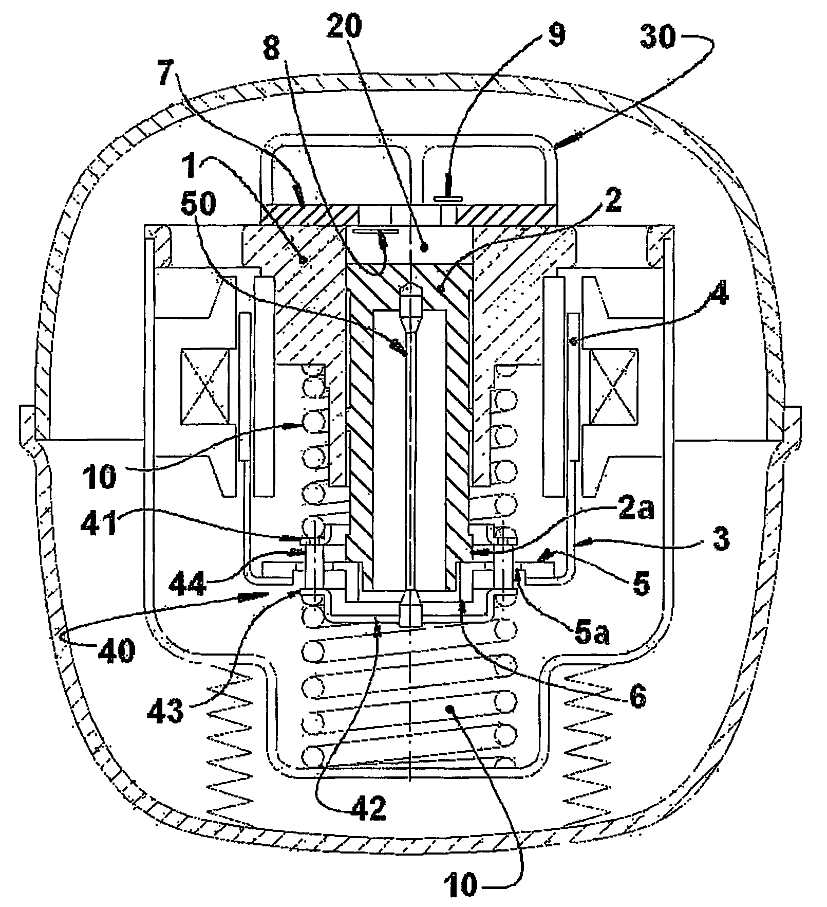
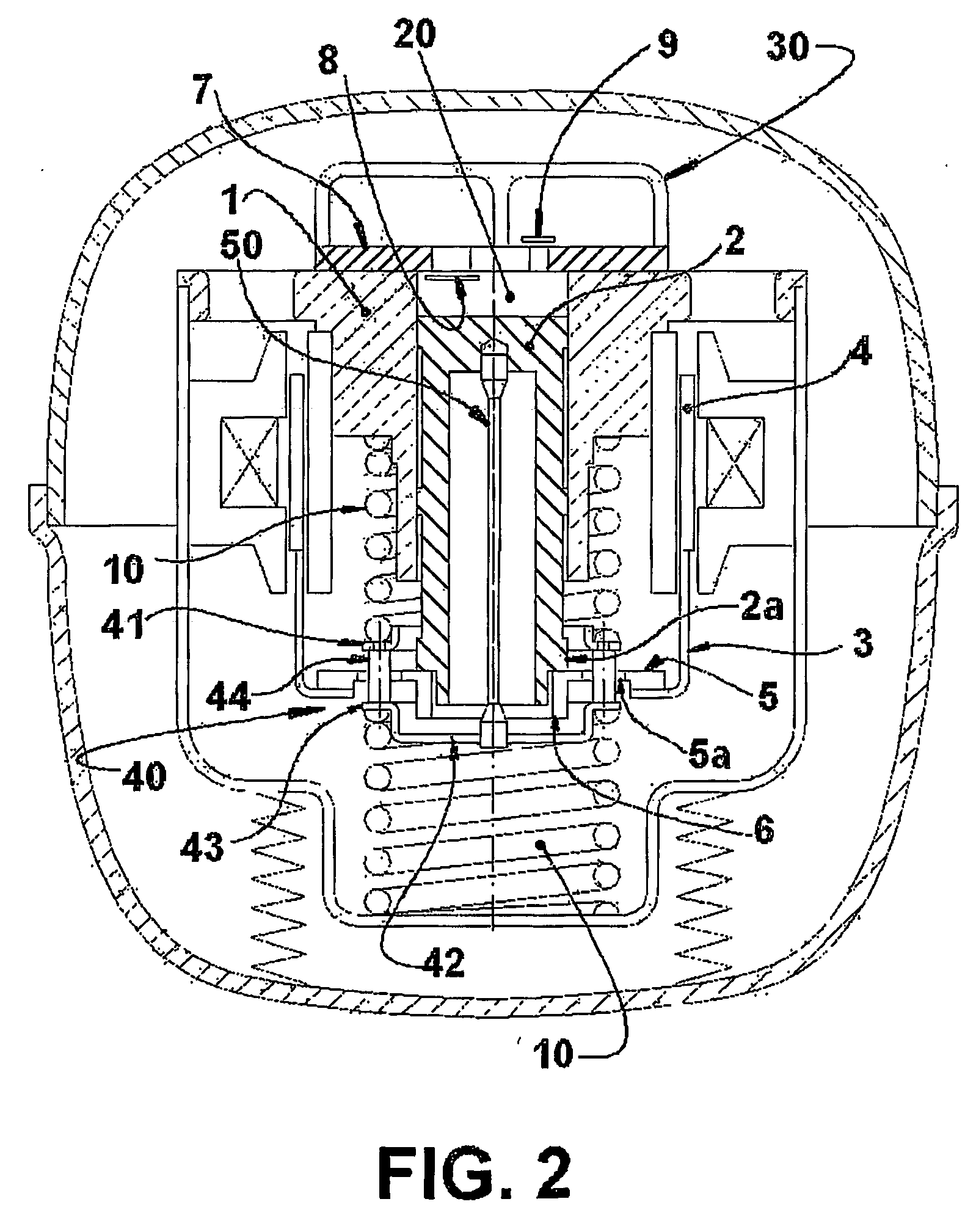
[0008] This and other objects are achieved through a reciprocating compressor driven by a linear motor comprising a hermetic shell, within which are mounted: a reference assembly formed by a motor and a cylinder; a resonant assembly formed by a piston reciprocating inside the cylinder, and by an actuating means operatively coupling the piston to the motor; and two spring means mounted to the resonant assembly and to the reference assembly and which are elastically and axially deformed in the displacement direction of the piston, said compressor comprising a mounting element coupling an end of one spring means (10) to an end of the other spring means (10); a coupling element, which has an end mounted to the piston and an opposite end mounted to the mounting element, said mounting element carrying the ends of the two spring means coupled thereto and being axially displaced together with the piston and displaced freely and transversally to the displacement direction of the piston, said coupling element being constructed to transmit the axial forces between the piston and the mounting element, and to minimize the application of radial forces to the piston.

Problems solved by technology

Such spring imperfections force the piston, causing friction and higher energy consumption, which impairs the performance of the linear compressor.

Method used


Image

  • Reciprocating compressor driven by a linear motor
  • Reciprocating compressor driven by a linear motor
  • Reciprocating compressor driven by a linear motor

Examples


Embodiment Construction

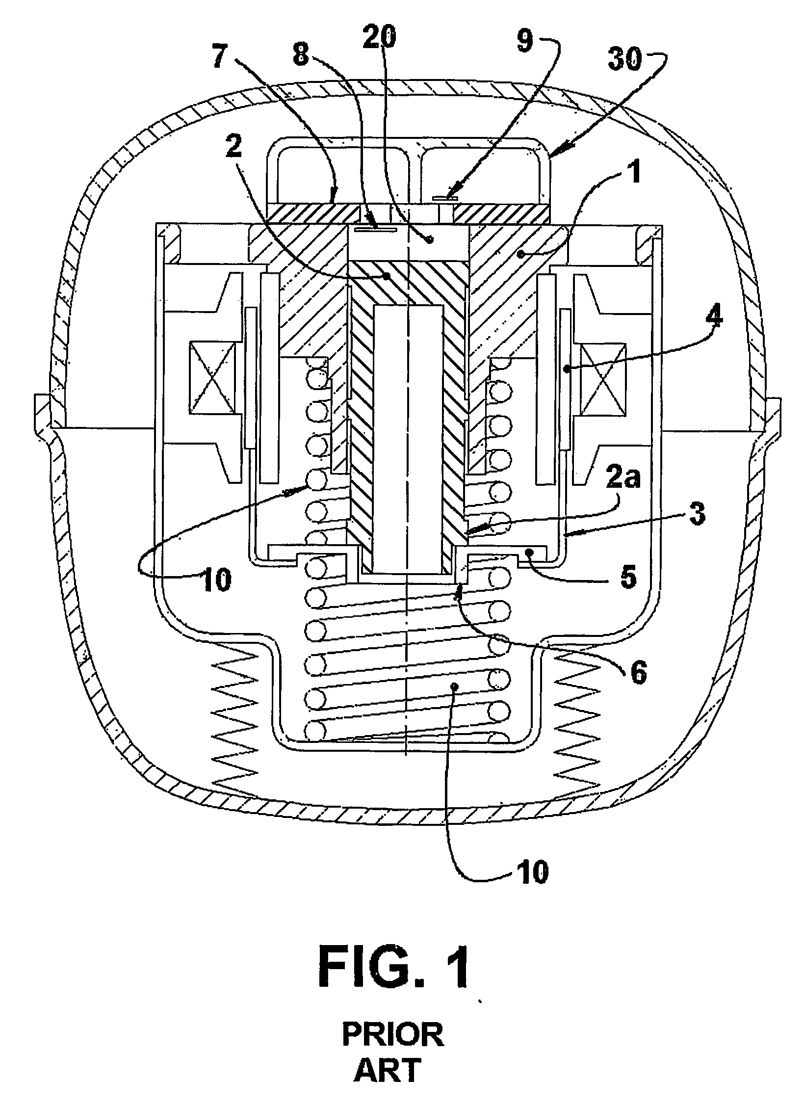
[0013] The present invention will be described in relation to a reciprocating compressor driven by a linear motor of the type used in refrigeration systems and comprising a hermetic shell, within which is mounted a motor-compressor assembly including a reference assembly affixed to the inside of said shell and formed by a linear motor and a cylinder 1, and a resonant assembly formed by a piston 2 reciprocating inside the cylinder 1 and by an actuating means 3 external to the cylinder 1 and which carries a magnet 4 to be axially impelled upon energization of the linear motor, said actuating means 3 operatively coupling the piston 2 to the linear motor, and the piston 2, such as illustrated, presenting a piston top portion and a tubular body portion.

[0014] In the construction illustrated in FIG. 1, the actuating means carries an annular disc 5, against which is coupled the piston 2, medianly defining a lower neck 6 for the fitting and fixation of a lower portion of the piston 2. In t...


PUM


Abstract

A reciprocating compressor driven by a linear motor, comprising a shell, within which are mounted: a reference assembly formed by a motor and a cylinder (1); a resonant assembly formed by a piston (2) reciprocating inside the cylinder (1), and by an actuating means (3) operatively coupling the piston (2) to the motor; two spring means (10) mounted to the resonant assembly and to the reference assembly and which are elastically and axially deformed in the displacement direction of the piston (2); a mounting element (40) coupling an end of one spring means (10) to an end of the other spring means (10); and a coupling element (50) mounted to the piston (2) and to the mounting element (40), which is axially displaced together with the piston (2) and displaced freely and transversally to the displacement direction of the piston (2), said coupling element (50) transmitting the axial forces between the piston (2) and the mounting element (40) and minimizing the application of radial forces to the piston (2).

Description

FIELD OF THE INVENTION [0001] The present invention refers, in general, to a reciprocating compressor driven by a linear motor to be applied to refrigeration systems and presenting a piston reciprocating inside a cylinder. More specifically, the invention refers to a coupling between the piston and a resonant system associated thereto. BACKGROUND OF THE INVENTION [0002] In a reciprocating compressor driven by a linear motor, the gas suction and gas compression operations are performed by the reciprocating axial movements of each piston inside a cylinder, which is closed by a cylinder head and mounted within a hermetic shell, in the cylinder head being positioned the suction and discharge valves that control the admission and discharge of the gas in relation to the cylinder. The piston is driven by an actuating means that supports magnetic components operatively associated with a linear motor affixed to the shell of the compressor. In some known constructions, each piston-actuating m...

Claims


Application Information

Patent Timeline
IPC IPC(8): F04B35/04F04B39/00
CPCF04B35/045Y10S417/902F04B39/0022F04B17/04F04B39/00
Inventor LILIE, DIETMAR ERICH BERNHARD
Owner EMPRESA BRASILEIRA DE COMPRESSORES SA (EMBRACO)
Learn More