
Information recording method and apparatus

a technology of information recording and information, applied in the field of information recording methods and apparatuses, can solve the problems of insufficient accuracy of recording regions, inability to provide accurate recording regions, and difficulty in improving the recording density, so as to achieve the effect of improving the recording density of optical recording mediums

Inactive Publication Date: 2005-06-09
LG ELECTRONICS INC
View PDF7 Cites 4 Cited by
  • Summary
  • Abstract
  • Description
  • Claims
  • Application Information

AI Technical Summary

Benefits of technology

The present invention provides an information recording method and apparatus that can improve the recording density of an optical recording medium. It can efficiently provide logical address information that changes with variations in recording density in unit record regions. It can also adaptively generate a write channel clock signal that changes with the volume of the recording medium. This allows for more efficient recording of user information onto the optical recording medium.

Problems solved by technology

However, information has to be recorded by corresponding one-to-one to a physical length of an ATIP frame preformatted onto an optical disc by a unit sub-code frame, accordingly it is difficult to improve a recording density more.
However, in the represented recording method, a write channel clock signal which has to vary in accordance with a variable length of unit record regions is not provided accurately.
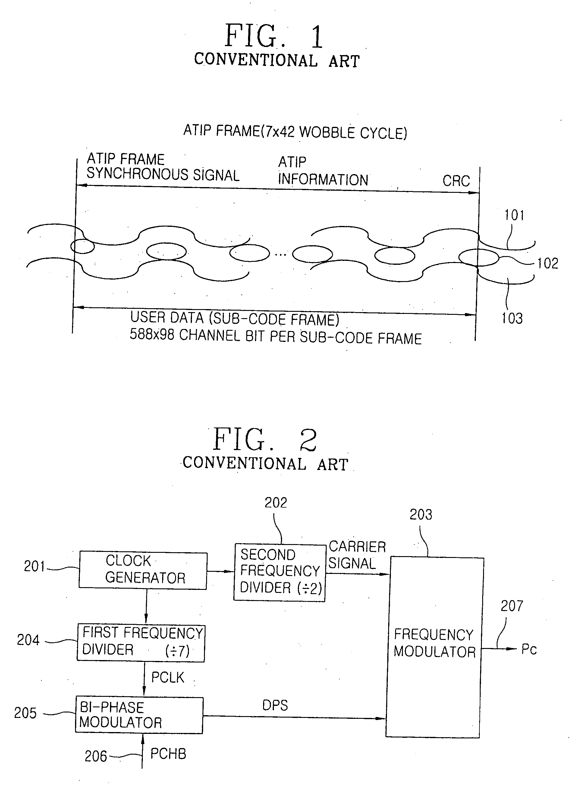
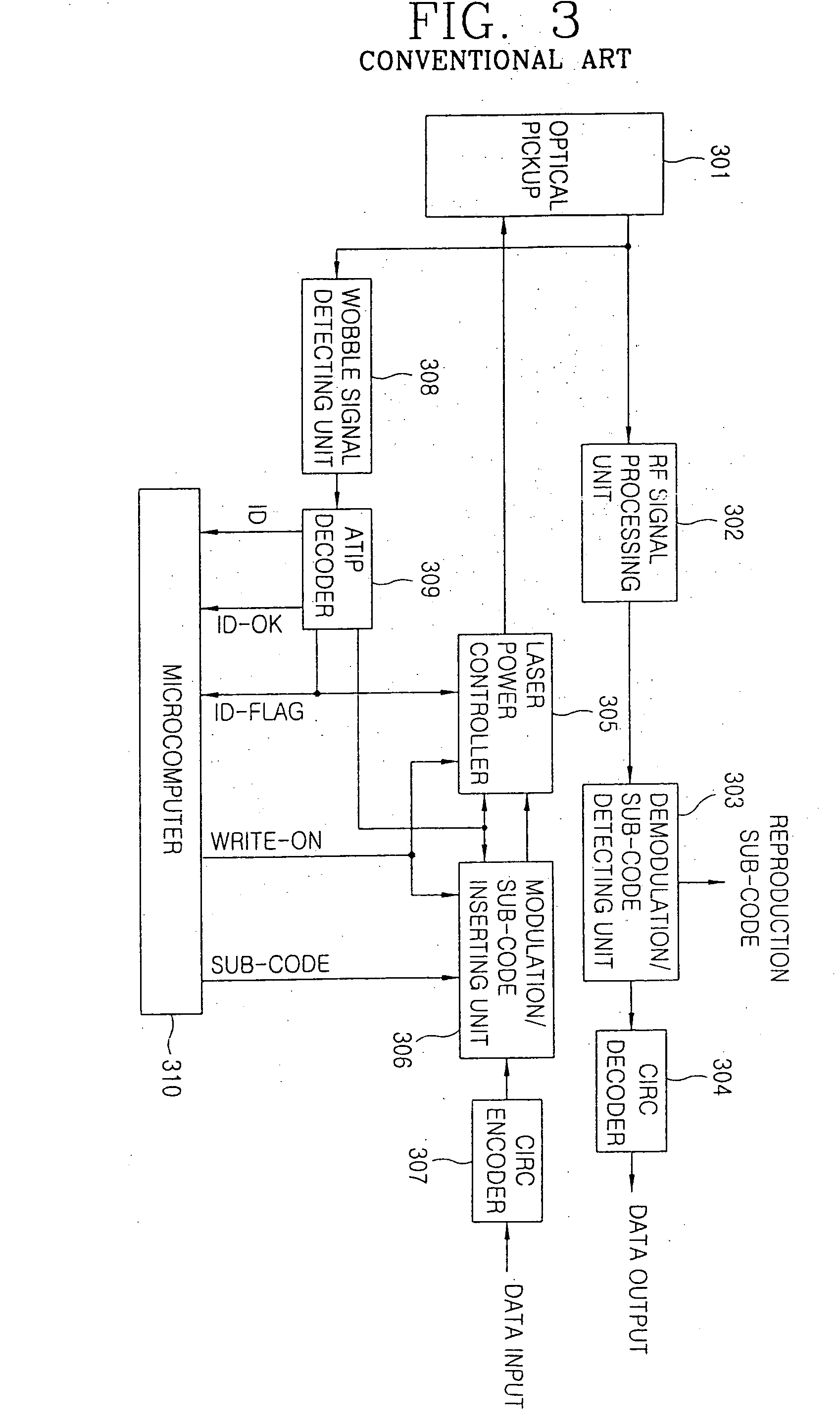
As described above, the information recording apparatus in accordance with the prior art has to record information so as to correspond one-to-one to a physical length of an ATIP (Absolute Time In Pre-groove) frame preformatted onto an optical disc by a unit sub-code frame, accordingly it is difficult to improve a recording density.
In addition, the information recording apparatus in accordance with the prior art can not provide accurately a write channel clock signal so as to vary in accordance with a variable length of a unit record region.

Method used


Image

  • Information recording method and apparatus
  • Information recording method and apparatus
  • Information recording method and apparatus

Examples


Embodiment Construction

[0061] Hereinafter, an information recording method and apparatus in accordance with the preferred embodiment of the present invention will now be described with reference to accompanying FIGS. 6˜10.

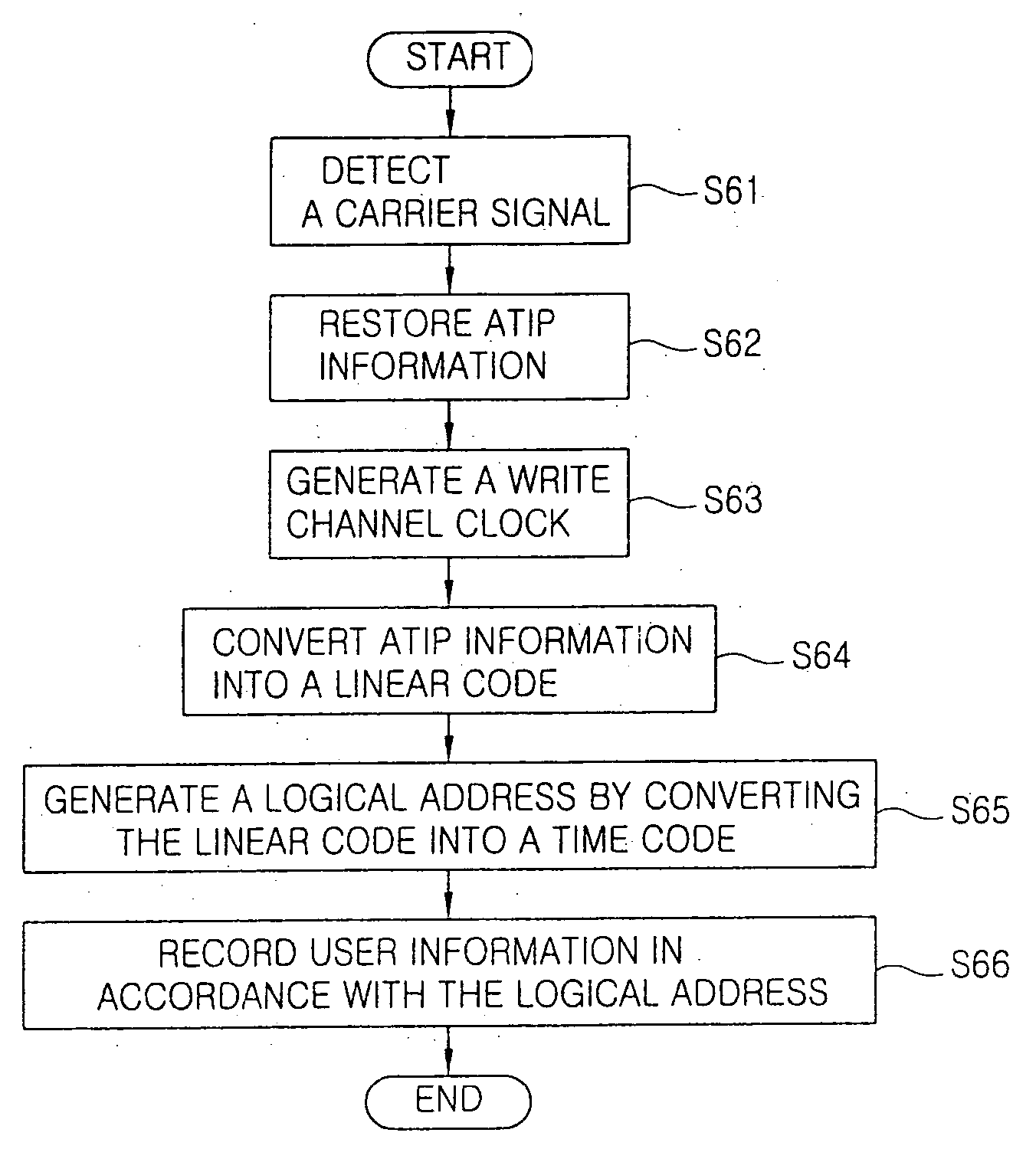
[0062]FIG. 6 is a flow chart illustrating an information recording method in accordance with the present invention.

[0063] First, a carrier signal (fc) of ATIP (Absolute Time In Pre-groove) information preformatted onto an optical recording medium is detected as shown at ST61. Herein, the ATIP information is displayed and preformatted onto the optical recording medium as time information.

[0064] The ATIP information is restored by frequency-demodulating the detected carrier signal (fc) and bi-phase-demodulating it as shown at S62. The restored ATIP information includes a synchronous signal (Synch), an ID code and an error correction code by a certain frame (data sector) unit. Herein, the ID code passes an error correction procedure in a demodulating process of the ATIP information.

[006...


PUM

PropertyMeasurementUnit
center frequencyaaaaaaaaaa
frequencyaaaaaaaaaa

Abstract

In an information recording method and apparatus which is capable of improving a recording density of an optical recording medium, a carrier signal is detected in an optical recording medium preformatted as first unit regions by modulating a synchronous signal dividing a track into first unit regions having a certain volume and address information indicating the first unit regions as time information format, and the address information is restored by the detected carrier signal. The restored address information is converted into a linear code, the converted linear code is counted with a clock signal varied in accordance with a volume of the second unit regions different from a volume of the first unit regions. Logical address information indicating the second unit regions is generated, and a record clock signal varied in accordance with a recording density of the second unit regions is generated, accordingly a recording density of an optical recording medium can improve.

Description

[0001] The present application is a continuation of co-pending U.S. patent application Ser. No. 10 / 780,710, filed on Feb. 19, 2004, which is a continuation of application Ser. No. 09 / 852,806 filed on May 11, 2001, for which priority is claimed under 35 U.S.C. § 120. This application also claims priority under 35 U.S.C. § 119(a) on Patent Application No. 25628 / 2000 filed in Korea on May 13, 2000. The entire contents of each of these applications are herein fully incorporated by reference.BACKGROUND OF THE INVENTION [0002] 1. Field of the Invention [0003] The present invention relates to a method for recording information onto a recording medium, and in particular to an information recording method and apparatus which is capable of improving a recording density of an optical recording medium. [0004] 2. Description of the Prior Art [0005] Generally, a CD (Compact Disc) recording and / or reproducing apparatus records and / or reproduces information by irradiating a laser light beam onto an...

Claims


Application Information

Patent Timeline
Patent Type & Authority Applications(United States)
IPC IPC(8): G11B7/0045G11B20/10G11B20/12G11B20/18G11B27/19G11B27/24G11B27/30
CPCG11B7/0045G11B20/10009G11B20/1217G11B20/18G11B27/24G11B27/3036G11B2220/2545G11B2020/1269G11B2020/1287G11B2020/1292G11B2020/183G11B2220/216G11B2220/218G11B27/3063
Inventor KIM, DAE YOUNG
Owner LG ELECTRONICS INC
Learn More