Underwater sounding apparatus

a sounding apparatus and underwater technology, applied in the field of underwater sounding apparatuses, can solve the problems of increasing the overall cost, deteriorating the detection performance, and unable to detect underwater target information

Inactive Publication Date: 2005-06-02
FURUNO ELECTRIC CO LTD
View PDF4 Cites 10 Cited by
  • Summary
  • Abstract
  • Description
  • Claims
  • Application Information

AI Technical Summary

Benefits of technology

[0022] The underwater sounding apparatus thus structured offers the same advantageous effects as the underwater sounding apparatus of the aforementioned first principal form of the invention. In this underwater sounding apparatus, the noise compensating signals are produced by adjusting one of the first and second reference signals whichever correlated strongly with the individual received signals (or the individual receiving beam signals) using the adjustment factors individually defined for the received signals (or for the receiving beam signals). This arrangement makes it possible to remove the propeller noise from the received signals (or the receiving beam signals) even when the influence of the propeller noise differs between the port side and the starboard side of a vessel or when the vessel has more than one propeller. According to the aforementioned second principal form of the invention, not only the first and second reference signals but also a third reference signal, a fourth reference signal, and so forth may be used for producing the noise compensating signals.
[0023] In another feature of the invention, the adjustment factors used in the underwater sounding apparatuses of the aforementioned first and second principal forms of the invention have values calculated by using received data on the reference signal or the first and second reference signals and each of the received signals (or each of the receiving beam signals) obtained when the propeller is kept turning.
[0024] With this arrangement, the adjustment factors are calculated by using the received data in such a way that the propeller noise contained in the adjusted reference signal becomes approximately equal to the propeller noise contained in each of the received signals (or each of the receiving beam signals).
[0025] In another feature of the invention, the adjustment factors used in the underwater sounding apparatus of the aforementioned first and second principal forms of the invention have values calculated by using a positional relationship between the propeller and each vibrating element, directional characteristics of each vibrating element and the wavelength of the transmitted acoustic waves.
[0026] With this arrangement, it is possible to obtain the adjustment factors even when the underwater sounding apparatus is not actually installed on a vessel or when the vessel with the apparatus installed is not moving.
[0027] In another feature of the invention, each of the adjustment factors used in the underwater sounding apparatus of the aforementioned first and second principal forms of the invention is the ratio of the complex amplitude of one of the received signals (or one of the receiving beam signals) to the complex amplitude of pertinent one of the reference signals or the first or second reference signals obtained when the propeller noise is approximated by sine waves having the same frequency as the frequency of the transmitted acoustic waves.

Problems solved by technology

Thus, the underwater sounding apparatus 80 conventionally has a problem that its detection performance is deteriorated by such false echoes caused by the propeller noise.
When this approach is applied to an underwater sounding apparatus employing a plurality of vibrating elements arranged in multiple rows and columns on a cylindrical outer surface of a transducer body, for example, there arises a problem that the propeller noise receiving transducer unit intervenes in propagation paths of transmitting and receiving beams, making it impossible to detect underwater target information.
In addition, the need for the provision of the dedicated propeller noise receiving transducer unit results in an overall cost increase due to an increase in the number of components.

Method used


Image

  • Underwater sounding apparatus
  • Underwater sounding apparatus
  • Underwater sounding apparatus

Examples


first embodiment

[0060] Referring first to FIGS. 1A-1B, 2, 3, 4 and 5A-5C, an underwater sounding apparatus 1 according to a first embodiment of the invention is described.

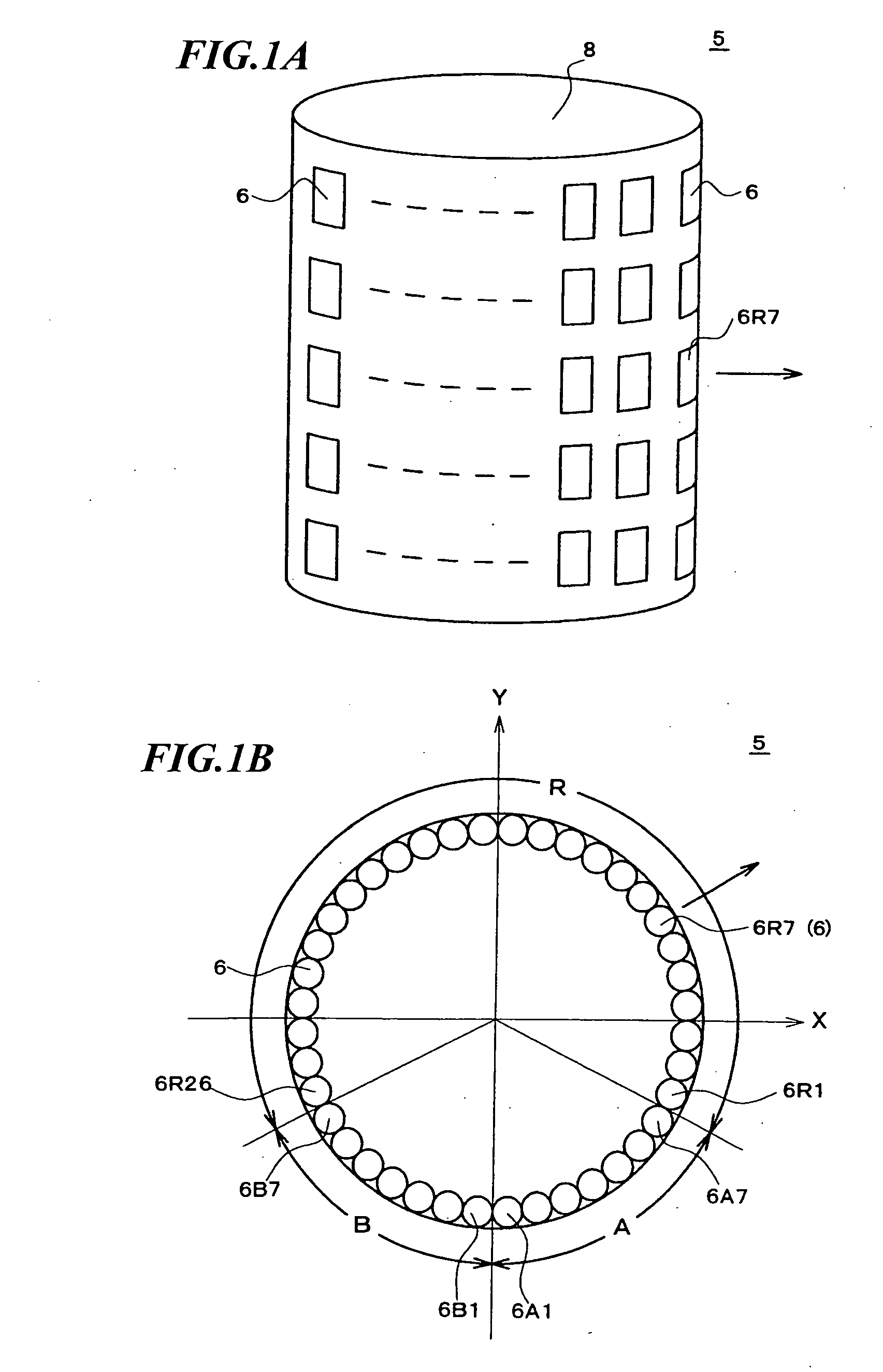
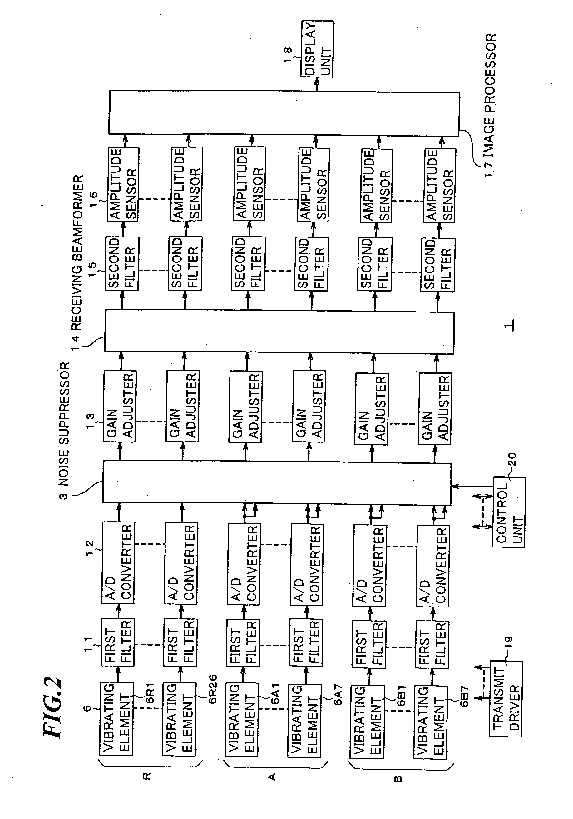
[0061]FIG. 1A is a perspective view of a transducer unit 5 of the underwater sounding apparatus 1 for transmitting and receiving ultrasonic sounding waves (acoustic waves). The transducer unit 5 has a transducer body 8 having a cylindrical outer surface on which a plurality of vibrating elements 6 oriented in specific directions are arranged in multiple rows and columns together forming a cylindrical array. In this embodiment, the vibrating elements 6 are arranged in 40 staves (vertical columns) by 5 rows. When sine-wave transmit signals are applied from a transmit driver 19 shown in a block diagram of FIG. 2 to the vibrating elements 6, the individual vibrating elements 6 oscillate, together forming a transmitting beam which is emitted into the body of water from the transducer unit 5. Acoustic waves emitted from the transducer ...

second embodiment

[0101] Referring now to FIGS. 8 to 18 an underwater sounding apparatus 1 according to a second embodiment of the invention is described, in which elements identical or similar to those of the first embodiment are designated by the same reference numerals.

[0102] While the adjustment factors are calculated for the individual received signals from data on the reference signals “A”, “B” and the received signals obtained with the propeller actually turned in the aforementioned first embodiment, adjustment factors are calculated from geometrical positions of a propeller 7 and the individual vibrating elements 6 on the assumption that a sine wave sound source emitting sine waves at the same frequency as the transmitting frequency of the transducer unit 5 is situated at the position of the propeller 7 (FIG. 9) in the second embodiment.

[0103] The underwater sounding apparatus 1 used in this embodiment is exactly the same in hardware configuration as shown in FIGS. 1A-1B, 2 and 3, except th...

third embodiment

[0143] Referring now to FIG. 19, an underwater sounding apparatus 1 according to a third embodiment of the invention is described, in which elements identical or similar to those of the aforementioned first and second embodiments are designated by the same reference numerals.

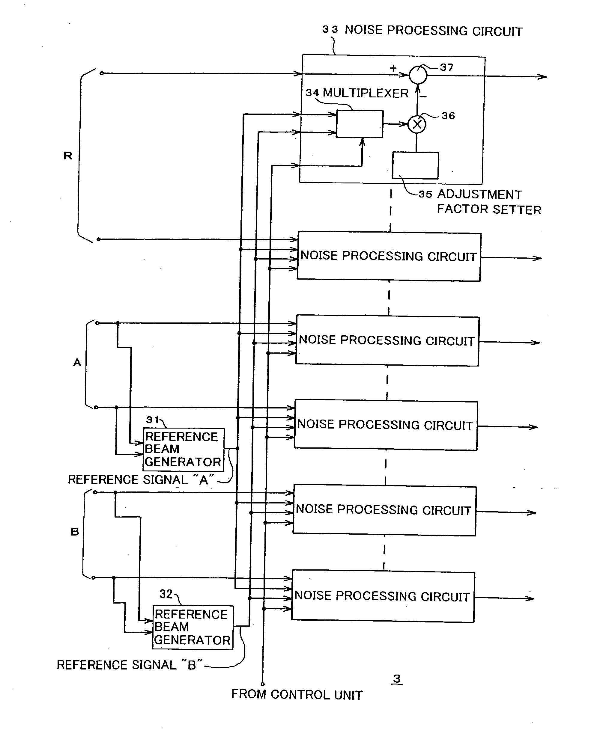
[0144] While the noise compensating signal is generated by multiplying the reference signal “A” or “B” by the adjustment factor in each noise processing circuit 33 (FIG. 3) in the first and second embodiments, a noise suppressor 3 of the underwater sounding apparatus 1 of the third embodiment includes noise processing circuits 33A which correspond to the noise processing circuits 33 of the first and second embodiments, each of the noise processing circuits 33A including a filter 38 which outputs a noise compensating signal when the reference signal “A” or “B” is input. The configuration of the underwater sounding apparatus 1 of the third embodiment is otherwise the same as those of the first and second embodime...


PUM


Abstract

While keeping a propeller located in a negative direction of a y-axis turning, transmission of acoustic waves from vibrating elements of a transducer unit is interrupted. Reference signals “A” and “B” which are receiving beam signals having principal acoustic axes oriented in a propeller direction are generated from received signals obtained by “A” and “B” group vibrating elements, respectively. Next, adjustment factors used for removing propeller noise from received signals obtained by vibrating elements on positive and negative sides of an x-axis are calculated by performing arithmetic operation on time-series data on the received signals obtained by the positive and negative sides vibrating elements and on time-series data on the reference signals “A” and “B”, respectively. When performing underwater sounding operation by transmitting acoustic waves, a product of the reference signal “A” or “B” and the adjustment factor is subtracted from the received signal obtained by each of the positive and negative sides vibrating elements, respectively.

Description

BACKGROUND OF THE INVENTION [0001] 1. Field of the Invention [0002] The present invention relates to an underwater sounding apparatus capable of eliminating the influence of propeller noise. 2. Description of the Prior Art [0003]FIG. 20 illustrates how an underwater sounding apparatus obtains information on an underwater situation, such as distribution of fish schools. Referring to FIG. 20, designated by the numeral 80 is an underwater sounding apparatus installed on a vessel 81, designated by the numeral 82 is an acoustic transducer unit of the underwater sounding apparatus 80, designated by the numeral 83 is a propeller of the vessel 81 and designated by the numeral 84 is a water surface. Also, designated by the letters Bt is a transmitting beam emitted from the transducer unit 82, designated by the letters Br is a receiving beam for receiving echo signals returned from underwater objects which reflect part of energy of the transmitting beam Bt and designated by the letter α is a ...

Claims


Application Information

Patent Timeline
IPC IPC(8): G01S7/521G01S7/526G01S7/527G01S15/96
CPCG01S7/521Y10S367/901G01S15/96G01S7/527
Inventor OKUNISHI, AKIRANISHIMORI, YASUSHIITO, YASUO
Owner FURUNO ELECTRIC CO LTD
Why Eureka
Try Eureka