Reinforcing structure, display device, and electronic apparatus
a technology of reinforced structure and display device, which is applied in the direction of identification means, electrical apparatus casings/cabinets/drawers, instruments, etc., can solve the problems of not taking into account the heat generated in the panel, and achieve the effects of easy formation, excellent cooling efficiency, and high reliability
- Summary
- Abstract
- Description
- Claims
- Application Information
AI Technical Summary
Benefits of technology
Problems solved by technology
Method used
Image
Examples
first embodiment
(First Embodiment)
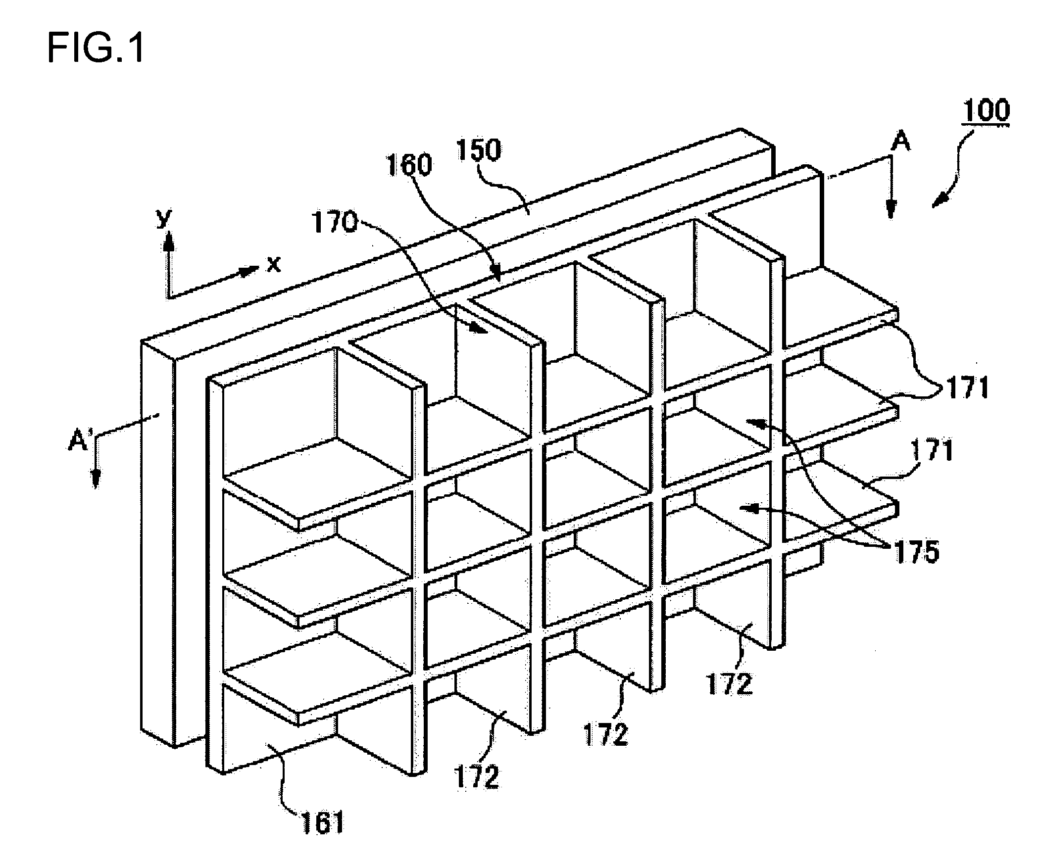
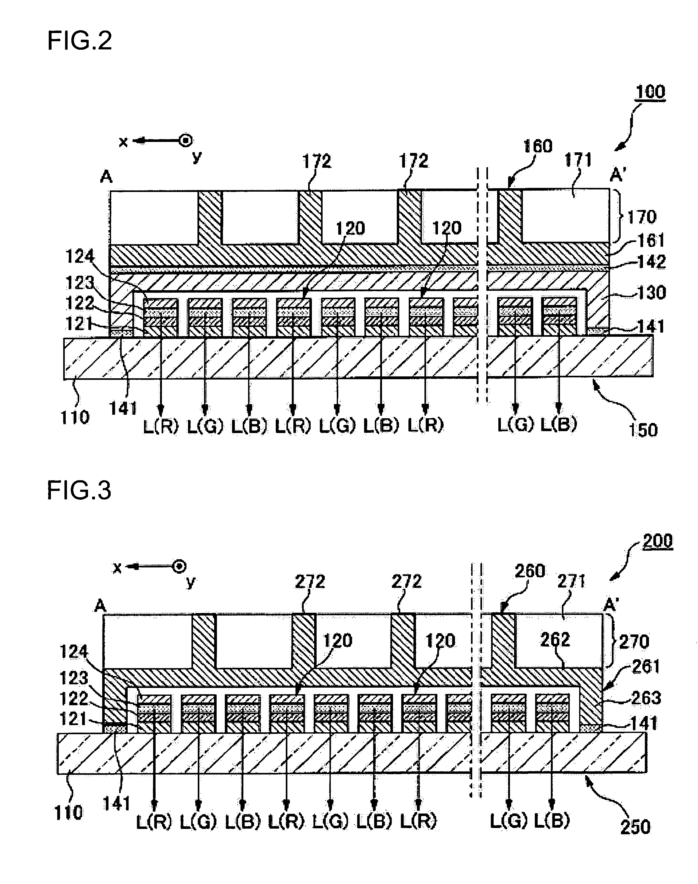
[0046]FIG. 1 is a perspective view illustrating the construction of an organic EL display device that is one embodiment of a display device according to the present invention, and FIG. 2 is a sectional constructional view taken along a line A-A′ in FIG. 1. An organic EL display device 100 shown in FIGS. 1 and 2 mainly comprises an organic electroluminescent panel (an organic EL panel) 150 that is a display panel, and a reinforcing structure 160 arranged on the backside (the side nearer to an observer in the drawing) of the panel.
[0047] The organic EL panel 150 is mainly composed of a substrate 110 having a light-transmitting property, a plurality of organic EL elements (light-emitting elements) 120 formed on the substrate 110, and a sealing member 130 applied to cover the organic EL elements 120 and hermetically adhered to the substrate 110 with a sealant 141 interposed therebetween. The organic EL panel 150 according to the present embodiment is of a so-called bo...
second embodiment
(Second Embodiment)
[0069] Next, a second embodiment of the present invention will be described with reference to FIG. 3.
[0070]FIG. 3 is a sectional view illustrating the construction of an organic EL display device (a display device) 200 of the present embodiment. The appearance of the organic EL display device 200 of the present embodiment is almost the same as that of the organic EL display device 100 shown in FIG. 1, and the sectional structure shown in FIG. 3 almost corresponds to a section taken along the line A-A′ in FIG. 1. In addition, elements in FIG. 3 similar to those in FIGS. 1 and 2 are given reference numerals similar to those in FIGS. 1 and 2, and the description thereof will be omitted.
[0071] The organic EL display device 200 mainly comprises an organic EL panel 250 and a reinforcing structure 260. The organic EL panel 250 is composed of a plurality of organic EL elements 120 which are arranged in a matrix in plan view on a substrate 110.
[0072] On the other hand, ...
third embodiment
(Third Embodiment)
[0076] Next, a third embodiment of the present invention will be described with reference to FIG. 4.
[0077]FIG. 4 is a perspective view illustrating the construction of an organic EL display device (a display device) 300 of the present embodiment. The organic EL display device 300 mainly comprises an organic EL panel 150 and a reinforcing structure 360 arranged on the backside of the panel. The organic EL panel 150 has the same construction as that of the organic EL panel according to the first embodiment. The description thereof will be omitted below.
[0078] The reinforcing structure 360 mainly comprises a metallic base plate (a supporting substrate) 361 adhered to a back face of the organic EL panel 150 and a metallic heat radiation member 370 which is integrally formed with an external surface (a surface nearer to an observer in FIG. 4) of the base plate 361. The heat radiation member 370 has a construction in which a plurality of (three in FIG. 4) first beam me...
PUM
 Abstract
Description
Claims
Application Information
 - R&D
- Intellectual Property
- Life Sciences
- Materials
- Tech Scout
- Unparalleled Data Quality
- Higher Quality Content
- 60% Fewer Hallucinations
Browse by: Latest US Patents, China's latest patents, Technical Efficacy Thesaurus, Application Domain, Technology Topic, Popular Technical Reports.
© 2025 PatSnap. All rights reserved.Legal|Privacy policy|Modern Slavery Act Transparency Statement|Sitemap|About US| Contact US: help@patsnap.com


