
Wireless communication system for media transmission, production, recording, reinforcement and monitoring in real-time

a communication system and wireless technology, applied in the field of wireless communication systems, can solve the problems of hindering the ability to effectively manage the system remotely, lan does not provide bi-directional communication between the transmitter and the receiver, and the wireless microphone system is limited to unidirectional transmission. , to achieve the effect of eliminating the subjectivity of locating, improving realism, efficiency and accuracy

Inactive Publication Date: 2005-05-26
GOSIESKI GEORGE J JR
View PDF10 Cites 65 Cited by
  • Summary
  • Abstract
  • Description
  • Claims
  • Application Information

AI Technical Summary

Benefits of technology

[0017] The present invention creates a paradigm shift by creating a digital, bi-directional communication system that combines a wireless media or multi-media system and wireless IEM system into one system. In one embodiment, the present invention comprises an access point, one or more clients, a network, an ear apparatus and system management software. The clients, e.g., transceivers, can be embodied as a body pack or handheld device, for example. In an illustrative embodiment, the ear apparatus can be integrated into a headset capable of holding a microphone. The present invention also provides a method for bi-directional communication between the remote components and the access point enabling remote system management. In one embodiment, the present invention can support dozens, if not a practically unlimited number of clients per access point.
[0018] In an illustrative embodiment, the present invention provides a Quality of Service (QoS) optimized for low latency, real time audio transmission, supports 802.11 protocols and standards (e.g., 802.11a, 802.11g, 802.11d, 802.11e, 802.11f, 802.11h, 802.11j, and 802.11n), supports 802.16 protocols and standards, transmits over unlicensed bands (e.g., ISM (Industrial, Scientific and Medical) band and U-NII (Unlicensed National Information Infrastructure) band), with the ability to operate in multi-band, multi-mode transmission mode, and can further transmit over the VHF or UHF bands. Further, in one embodiment, the present invention can process media in a continuous stream without packetization based on these protocols.
[0020] In one embodiment, the present invention uses phased array antennas to reduce power consumption, increase range, and track transceiver location while improving immunity to interference. Also, the present invention can further provide signal encryption for secure transmissions in compliance with AES standards. In an illustrative embodiment, the present invention supports AES / EBU standards for transmitting digital audio. In another embodiment, the invention also supports AES-47. In one embodiment, the present invention can provide for transmitted sampling rates of 48 kHz, 96 kHz, and 192 kHz with a 24-bit resolution. Higher sampling rates can also be accommodated. Sample rates and sample formats can be selected automatically using the system management programming of the present invention, or manually such as by an engineer, for example. In terms of video quality, the present invention can support formats such as SDTV and HDTV, for example.
[0022] In addition to the above advantages, the present invention provides a level of flexibility, scalability, and upgradeability unavailable in today's multi-media industry using modular plug and play sub-systems, on-line firmware and software upgrades. The present invention further provides an open source software platform to allow third party development of plug-ins. The present invention also tracks, sequences, and records an engineer's settings and preferences, allowing this information to be stored as a group and recalled at a later date. Groups can be sequenced and stored for future use as super sets, i.e., scenes. In one embodiment, this capability encompasses lighting systems and audio / visual equipment. The present invention further allows for remote management of user devices by an engineer or technician, for example.
[0023] Further, the present invention can create an acoustic or visual model for a venue and store it in a database for future reference. The model can store characteristics for the space, such as reverberation, hot spots, harmonics, standing waves, lighting effects, pan and zoom range, and other audio and visual characteristics as are known in the art. In one embodiment, the present invention analyzes and recommends parameter settings for a particular venue based on a system generated acoustic and / or visual model of the venue, a stored record of the engineer's typical settings and preferences, and the engineer's settings and preferences for that venue and venues with similar acoustic and / or visual models. The present invention can automatically scan a venue to evaluate the local RF environment, ranking potential sources of interference, recommending interference free, intermodulation free settings, configuring the RF components to maximize reception and immunity, and providing dynamic channel selection and dynamic RF power regulation. By providing for dynamic channel selection and dynamic modulation, the present invention assists in maximizing the spectral efficiency of the available bandwidth. With higher and higher efficiencies, the required power decreases; as such, the present invention assists with power management in connection with the present invention.
[0025] In addition, the present invention can track the position of active transceivers and use this information to automatically adjust control surface panning controls. This capability effectively eliminates the subjectivity of locating and tracking a media source within the sound or visual field of a stereo, surround sound or visual recording, broadcast, or reinforcement system, thereby improving realism, efficiency, and accuracy. The present invention further provides digital interfaces operable to comply with AES, Firewire 2, Ethernet, and ATM standards.

Problems solved by technology

This requires significant resources to install and manage, including large amounts of supporting equipment and facility infrastructure capable of routing cables and housing and cooling all of this equipment, as well as significant power requirements and conditioning.
Today's wireless microphone systems are limited to unidirectional transmission, broadcast over the very-high frequency (VHF) or ultra-high frequency (UHF) band, using FDM (Frequency Division Multiplexing).
The LAN does not provide bi-directional communication between the transmitter and its receiver.
Such distributed control and unidirectional communication hinders the ability to effectively manage the system remotely.
Additionally, transmitter power consumption has continued to trend downward, extending the operating life of these devices.
While wireless microphone systems having the above basic capabilities are known and currently available, analog to digital signal conversion for wireless microphone systems has only recently become available in a very limited number of products.
This product is unidirectional and uses a proprietary modulation over the UHF band.
System bulkiness and specifications limit its use to conference environments—e.g., it requires a proprietary microphone, twelve (12) AA batteries per transceiver, and has a frequency response of 70-10 kHz.
Today's wireless IEM systems are limited to unidirectional transmission.
Unlike wireless microphone systems, current IEM systems do not incorporate Ethernet technology into the transmitter, resulting in the inability to remotely monitor the IEM system.
Further, current IEM systems do not integrate a wireless microphone system or wireless visual system of any type, and do not provide analog to digital or digital to analog conversion, signal encryption, bi-directional transmission, remote monitoring, or remote management.
Current video systems, like audio systems, are also limited to unidirectional transmission.
This is beyond the current systems, which are unidirectional, analog, stand-alone, limited in range, one transmitter to one receiver, and have limited audio and visual quality.

Method used


Image

  • Wireless communication system for media transmission, production, recording, reinforcement and monitoring in real-time
  • Wireless communication system for media transmission, production, recording, reinforcement and monitoring in real-time
  • Wireless communication system for media transmission, production, recording, reinforcement and monitoring in real-time

Examples


Embodiment Construction

[0030] In one embodiment, the present invention provides a digital wireless media system and a digital wireless IEM system eliminating the redundancy resulting from separate and independent wireless audio, visual and IEM systems while improving signal quality, system reliability, system management, and increasing functionality.

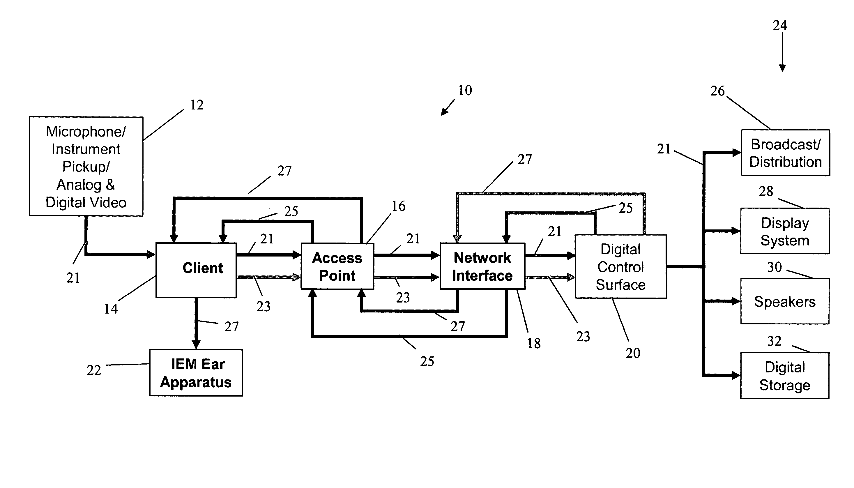
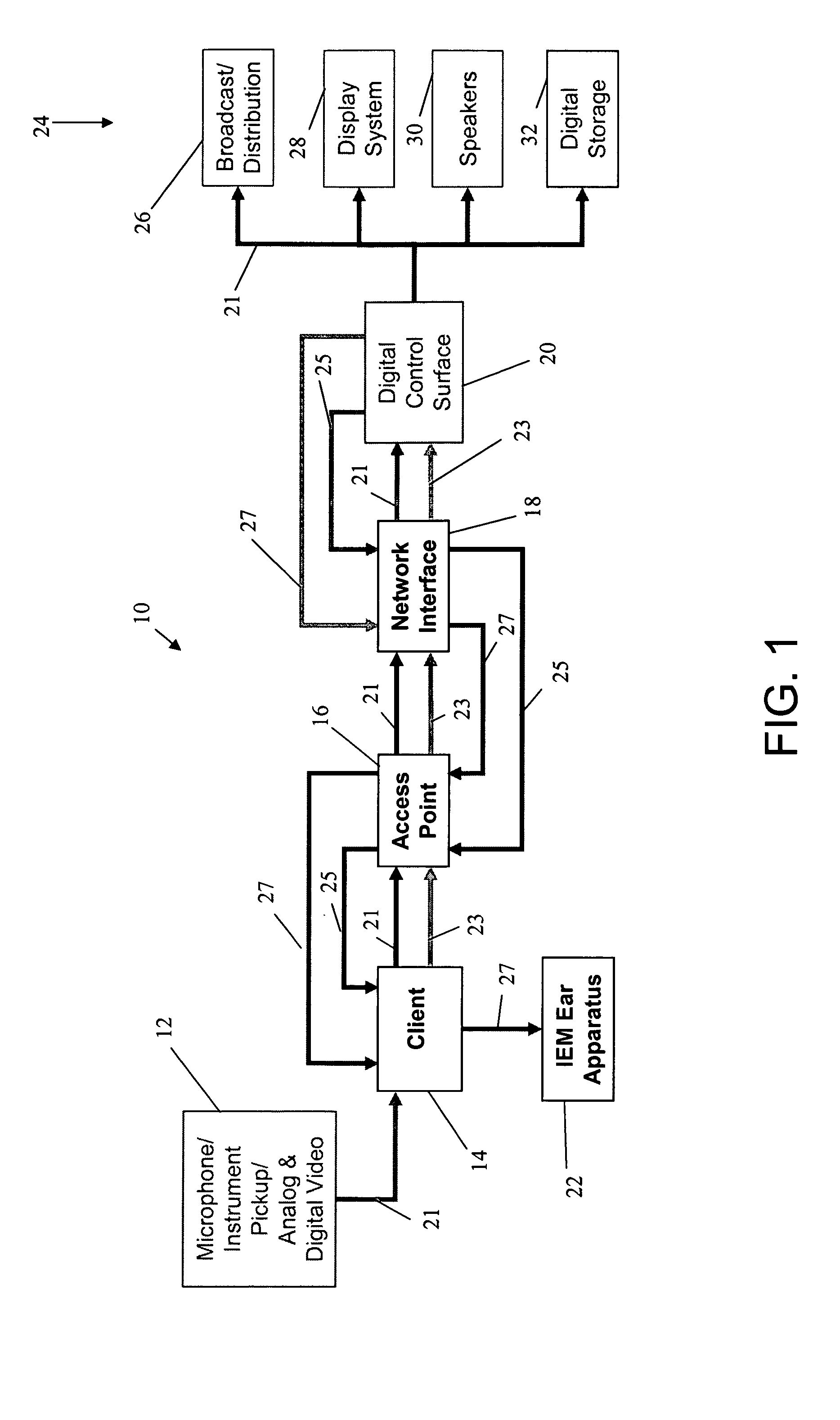
[0031] As shown in FIG. 1, the present invention can comprise a system 10 including, in one embodiment, an input device 12, a client 14, an access point 16, a network interface 18, a control surface 20, an IEM ear apparatus 22 and output elements 24. Input device 12 can be, for example, a microphone, an instrument pickup, a still camera, a video camera, and other known devices for receiving audio and visual data. Client 14 can be one or more transceivers in the form of a body pack or handheld transceiver, for example. Access point 16 can be a base station, for example, and ear apparatus can comprise earbuds or ear pieces as are commonly known in the art. In o...


PUM


Abstract

A digital, bi-directional, full duplex communication system employs a wireless media system and wireless IEM system. In one embodiment, the present invention comprises an access point, one or more clients, an ear apparatus and system management software. The present invention also provides a method for bi-directional communication between the remote components and the access point enabling remote system management.

Description

CROSS-REFERENCE TO RELATED APPLICATIONS [0001] This application claims priority under 35 USC 119(c) of U.S. patent application Ser. No. 60 / 524,779, entitled “Wireless Sound System for Transmission, Production, Recording and Monitoring in Real-Time”, filed Nov. 25, 2003 and incorporated herein by reference.TECHNICAL FIELD [0002] The present invention relates to wireless communication systems, and more particularly, to a bi-directional, full duplex, digital communication system which can incorporate a wireless audio system, wireless visual media system and an in-ear monitoring system for enhanced audio and visual media transmission, production, recording, reinforcement and monitoring in real-time. BACKGROUND ART [0003] Professional multi-media systems and multi-media control can be applied in environments as diverse as concert halls, stadiums, clubs, convention centers, conferencing centers, open air spaces, houses of worship, meeting spaces (government-, corporate-, and private-secto...

Claims


Application Information

Patent Timeline
IPC IPC(8): H04L12/26H04L12/28H04L29/06H04H60/04
CPCH04L29/06027H04L43/08H04M1/6058H04M1/6066H04M1/725H04R2201/107H04W84/12H04W88/08H04L65/80H04R1/1091H04R5/033H04W24/00H04L65/1101
Inventor GOSIESKI, GEORGE J. JR.PERRETTA, JOHN RAND
Owner GOSIESKI GEORGE J JR
Learn More