Eureka AIR delivers breakthrough ideas for toughest innovation challenges, trusted by R&D personnel around the world.

Hearing compensation system incorporating signal processing techniques

a signal processing and compensation system technology, applied in the field of electronic systems for sound reproduction and electronic hearing devices, can solve the problems of inability to hear in the presence of noise, no approach to enhance speech intelligibility, and no approach to hearing aid users

Inactive Publication Date: 2005-05-26
BRIGHAM YOUNG UNIV
View PDF99 Cites 159 Cited by
  • Summary
  • Abstract
  • Description
  • Claims
  • Application Information

AI Technical Summary

Problems solved by technology

One of the most common complaints made by hearing aid users is the inability to hear in the presence of noise.
One researcher, Mead Killion, has noted that none of these approaches has enhanced speech intelligibility.
With these techniques, researchers have generally noted a decrease in speech intelligibility testing when noise contaminated speech is processed, despite the fact that measures of quality or preference increase.
It has been demonstrated that acoustic signals can be successfully processed according to these techniques to enhance voiced or vowel sounds in the presence of white or impulsive noise, however, these techniques are less successful in preserving unvoiced sounds such as fricatives or plosives.
Switching between the gain mechanisms in each of these sound intensity regions has introduced significant distracting artifacts and distortion in the sound.
Therefore, the application of gain schemes which attempt to use a frequency band wider than a single critical band (i.e., critical band as defined in Fundamentals of Hearing, An Introduction, Third Edition, William A. Yost, Academic Press, page 307 (1994), cannot produce the optimum hearing sensation in the listener.
Failure to properly account for the adaptive full-range compression will result in degraded hearing or equivalently, loss of fidelity and intelligibility perceived by the hearing impaired listener.
Therefore, mechanisms as disclosed, which do not provide a sufficient number of frequency bands to compensate for hearing losses, will produce sound which is of less benefit to the listener in terms of the quality (user preference) and intelligibility.
This FFT implementation is complex and likely not suitable for low-power battery applications.
As known to those skilled in the art, prior-art FFT implementations introduce a block delay by gathering and grouping blocks of samples for insertion into the FFT algorithm.
This block delay introduces a time delay into the sound stream which may be long enough to be annoying and to induce stuttering when one tries to speak.
An even longer delay could occur which sounds like an echo when low levels of compensation are required for the hearing impaired individual.
For acoustic input levels below hearing threshold (i.e. soft background sounds which are ever present), the FFT implementation described above provides excessive gain.
This results in artifacts which add noise to the output signal.
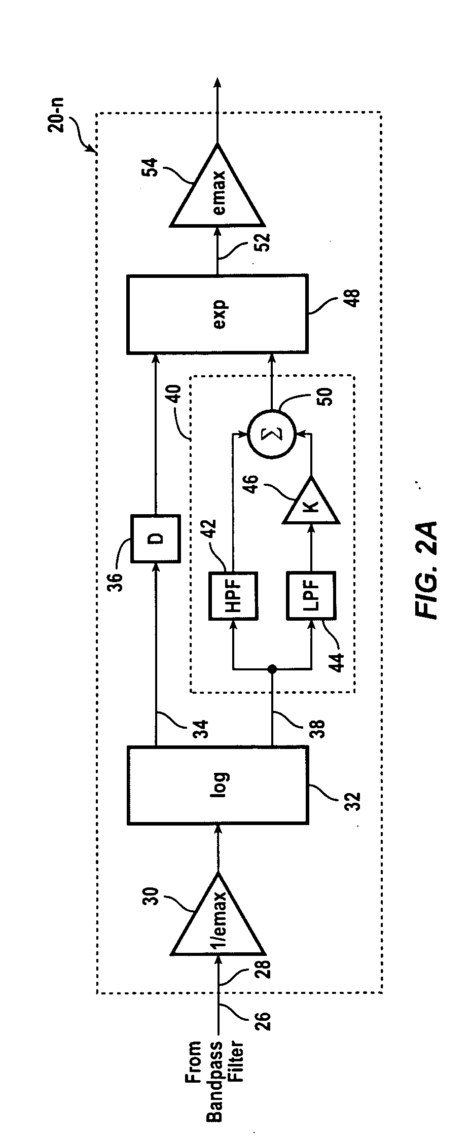
While the component parts that are required to assemble a high fidelity, full-range, adaptive compression system have been known since 1968, no one has to date proposed the application of the multiplicative AGC to the several bands of hearing to compensate for hearing losses.
An in-the-ear hearing aid must operate on very low power and occupy only the space available in the ear canal.
To date, this high efficiency has been achieved at the expense of extremely poor frequency response.
These resonances significantly contribute to the feedback oscillation so commonly associated with hearing aids, and subject signals in the vicinity of the resonant frequencies to severe intermodulation distortion by mixing them with lower frequency signals.

Method used


Image

  • Hearing compensation system incorporating signal processing techniques
  • Hearing compensation system incorporating signal processing techniques
  • Hearing compensation system incorporating signal processing techniques

Examples


Embodiment Construction

[0058] Embodiments of the present invention are described herein in the context of a hearing compensation system incorporating signal processing techniques. Those of ordinary skill in the art will realize that the following detailed description of the present invention is illustrative only and is not intended to be in any way limiting. Other embodiments of the present invention will readily suggest themselves to such skilled persons having the benefit of this disclosure. Reference will now be made in detail to implementations of the present invention as illustrated in the accompanying drawings. The same reference indicators will be used throughout the drawings and the following detailed description to refer to the same or like parts.

[0059] In the interest of clarity, not all of the routine features of the implementations described herein are shown and described. It will, of course, be appreciated that in the development of any such actual implementation, numerous implementation-spe...


PUM


Abstract

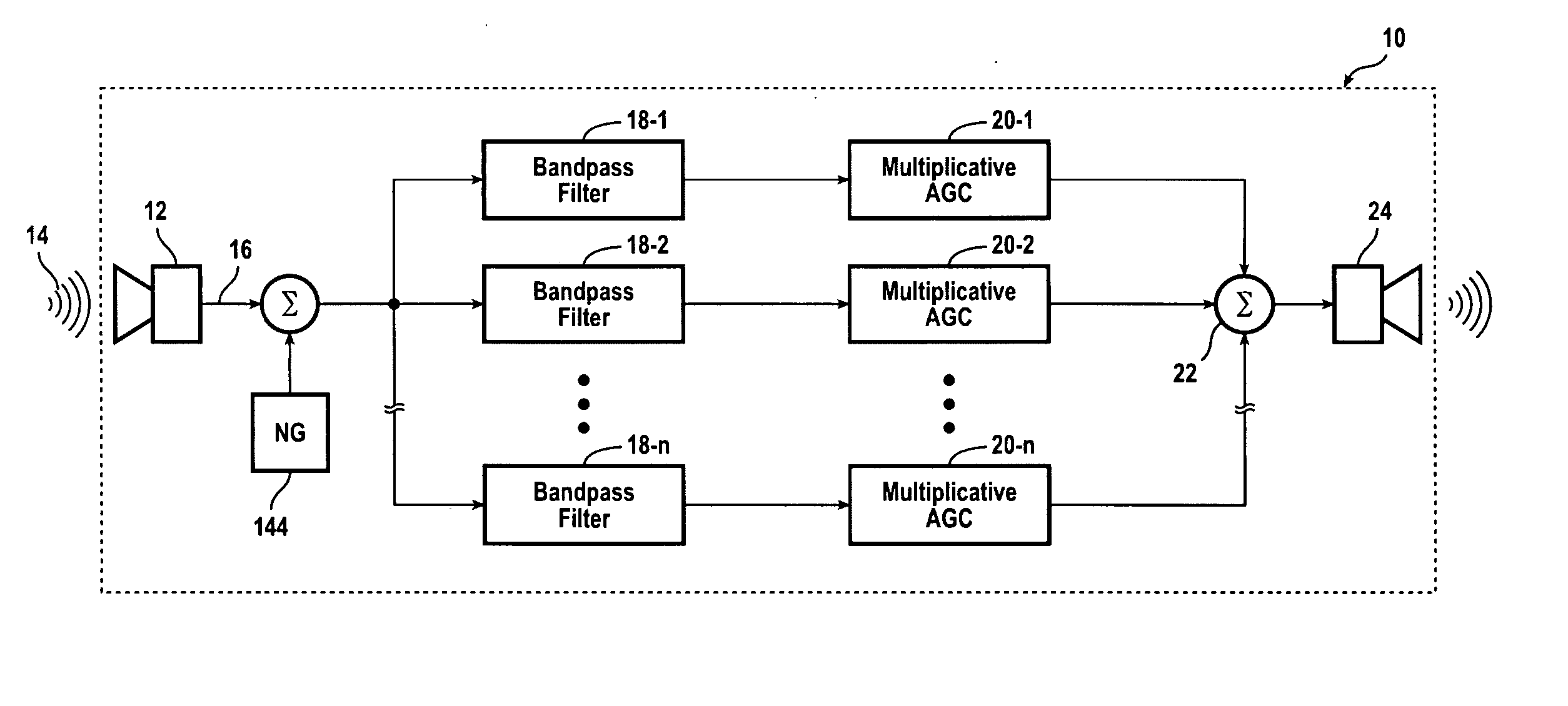
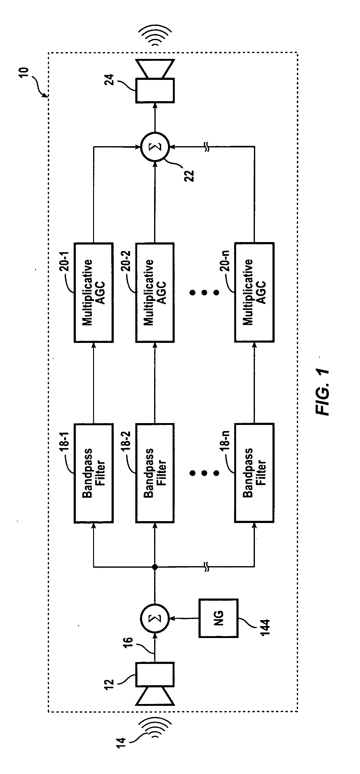
A hearing compensation system comprises a plurality of bandpass filters having an input connected to an input transducer and each bandpass filter having an output connected to the input of one of a plurality of multiplicative automatic gain control (MAGC) circuits whose outputs are summed together and connected to the input of an output transducer. The MAGC circuits attenuate acoustic signals having a constant background level without the loss of speech intelligibility. The identification of the background noise portion of the acoustic signal is made by the constancy of the envelope of the input signal in each of the several frequency bands. The background noise that will be suppressed includes multi-talker speech babble, fan noise, feedback whistle, florescent light hum, and white noise. For use in the consumer electronics field background acoustic noise may be sensed and used to adjust gain in the various MAGC circuits so as to improve a user's listening experience, whether the user is hearing impaired or not.

Description

RELATED APPLICATIONS [0001] This application is a continuation-in-part of co-pending U.S. patent application Ser. No. 09 / 444,972, filed Nov. 22, 1999, which is, in turn, a continuation-in-part of U.S. patent application Ser. No. 09 / 169,547, filed Sep. 9, 1998 (now abandoned) which is, in turn, a continuation-in-part of U.S. patent application Ser. No. 08 / 697,412, filed Aug. 22, 1996 (now U.S. Pat. No. 6,072,885) which is, in turn, a continuation-in-part of U.S. patent application Ser. No. 08 / 585,481, filed Jan. 12, 1996 (now U.S. Pat. No. 5,848,171) which is, in turn, a continuation of U.S. patent application Ser. No. 08 / 272,927, filed Jul. 8, 1994 (now U.S. Pat. No. 5,500,902).BACKGROUND OF THE INVENTION [0002] The present invention relates to electronic hearing devices and electronic systems for sound reproduction. More particularly, the present invention relates to noise suppression to preserve the fidelity of signals in electronic hearing aid devices and electronic sound systems...

Claims


Application Information

Patent Timeline
IPC IPC(8): H03G9/02H04R25/00
CPCH03G9/005H04R2430/03H04R25/356H03G9/025
Inventor CHABRIES, DOUGLAS MELVINCHRISTIANSEN, RICHARD WESLEY
Owner BRIGHAM YOUNG UNIV
Why Eureka
Eureka Blog
Learn More