
System to control daylight and artificial illumination and sun glare in a space

a technology of artificial illumination and space, applied in the field of space control system, can solve the problems of maintenance problems, closed loop system, unsuitable open loop system for window treatment control, etc., and achieve the effect of reducing the overall system cost, optimal illumination control of the space, and controlling the sun glare in the interior spa

Active Publication Date: 2005-05-26
LUTRON TECH CO LLC
View PDF17 Cites 235 Cited by
  • Summary
  • Abstract
  • Description
  • Claims
  • Application Information

AI Technical Summary

Benefits of technology

[0009] A further advantage of the present invention is that the overall illumination in the space can be maintained for multiple lighting profiles. Each of these lighting profiles can have different requirements for the overall illumination and the relations of illuminations in different portions of the space.
[0010] Two exemplary embodiments for the electric light control implementation are described herein, although variations of these embodiments will be apparent to those of skill in the art based on the descriptions contained herein. These embodiments may employ control options defined as “open loop” control and “closed loop” control. The term “open loop” is used to describe an electric light control system based on signals from interior light sensors that predominantly sense daylight entering the space. The term “closed loop” refers to electric light level control systems using interior light sensors which predominantly sense a combination of daylight entering the space and the light generated by the electric light sources being controlled.
[0011] The invention also describes a closed loop system for control of window shading devices. It is assumed that such closed loop system is implemented based on the light readings from a light sensor sensing dominantly daylight entering the space through the windows affected by the window treatments being controlled. Therefore the sensor incident illumination changes as a consequence of window treatment adjustment.
[0012] Based on one embodiment of the present invention the control of both the plurality of electric lights and window treatments can be achieved using only a single photosensor or a single averaged reading from a plurality of interior sensors. Thus the single signal (single input variable) from a single light sensor or group of light sensors can be used as an input for a closed loop algorithm for control of window treatments and an open loop algorithm for control of electric lights.
[0013] As discussed above, one of the problems with prior art systems is that exterior light sensors and predictive control algorithms are employed for control of window treatments. As described above, these systems require maintenance of exterior sensors and complex data gathering and setup procedures. The control approach of the present invention eliminates the need for exterior sensors and these data gathering and setup procedures, thus reducing the overall system cost.
[0014] In addition, the present invention also allows sun glare in the interior space to be controlled. The present invention can provide near optimal illumination control of the space. Furthermore, the properties of the space such as the aperture ratios or openings, geometric orientation of the windows or exterior shading objects do not need to be known prior to the installation and commissioning of the system. Both illumination and glare can be controlled without significantly sacrificing energy savings resulting from the use of daylight or interior illumination. The system has the potential to automatically recalibrate based on immediate or repeated occupant input resulting in increased occupant satisfaction.

Problems solved by technology

One of the major problems of illumination maintenance systems, and in particular, closed loop (feedback) illumination maintenance systems, is the variation of incident light at the sensor or sensors employed for detecting the incident light due to occupants moving in the space or some other type of variation of surface reflections in the space.
Further, open loop systems have been developed for illumination maintenance and daylight harvesting but such open loop systems are not suitable for window treatment control implemented based on the interior light sensors because when a shading or window treatment device is closed, access to exterior lighting conditions is prevented or restricted.
Exterior light sensors cause maintenance problems and require exterior wiring.
Predictive control schemes are difficult to configure.
Some of the problems with this type of control are that it demands maintenance of exterior photo sensors exposed to the elements and there are problems with wiring and / or mounting sensors continuously exposed to the outside lighting conditions.
Furthermore, preparation and creation of complex databases is required to define the lighting conditions for each space of a building throughout a year for large buildings, which is time consuming and expensive.
Further, these systems require control database modifications in case exterior shading objects are added such as new buildings or plants and further, the controls cannot be fully optimized for each space of a large building and therefore do not result in optimal occupant comfort and energy savings.

Method used


Image

  • System to control daylight and artificial illumination and sun glare in a space
  • System to control daylight and artificial illumination and sun glare in a space
  • System to control daylight and artificial illumination and sun glare in a space

Examples


Embodiment Construction

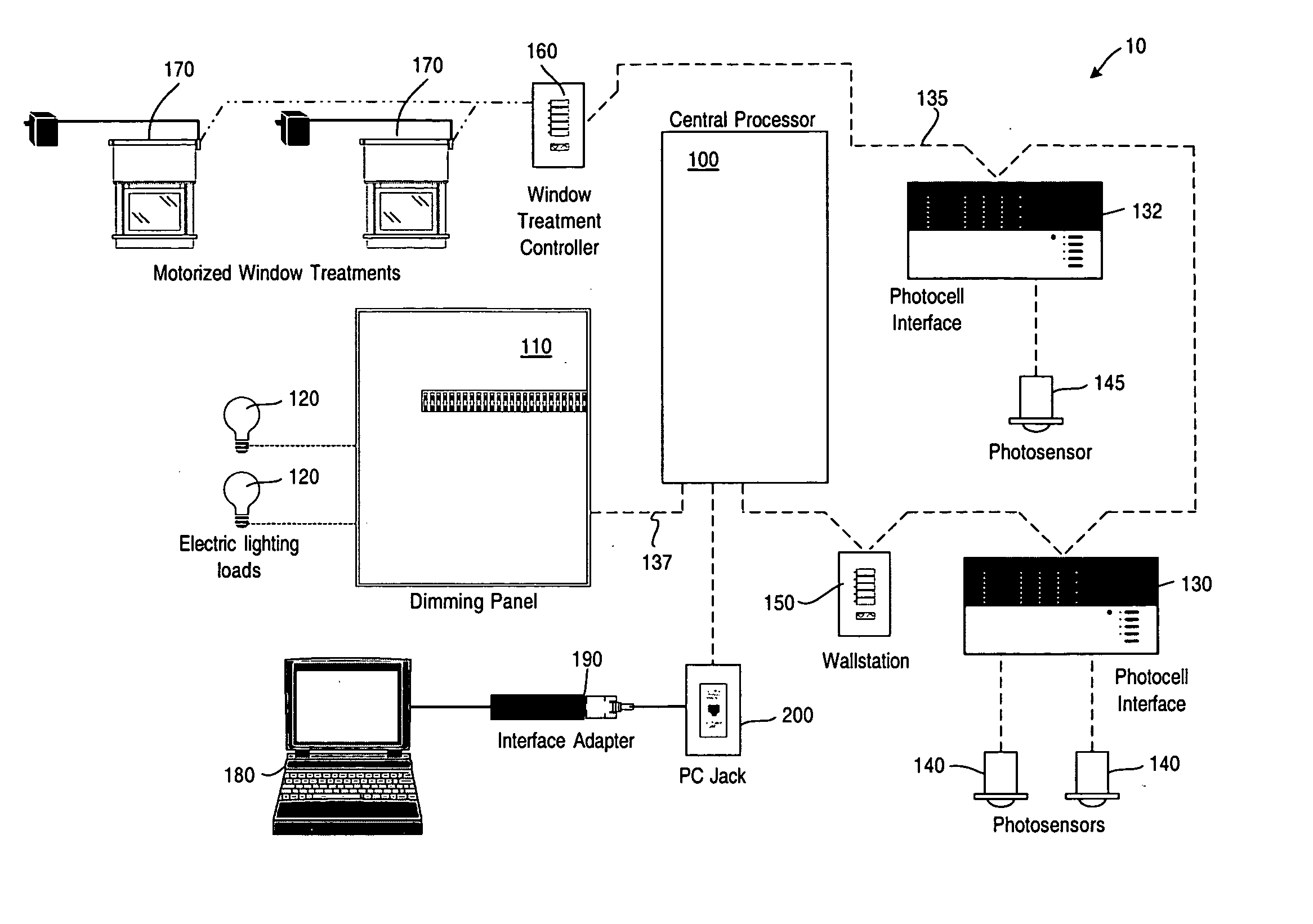
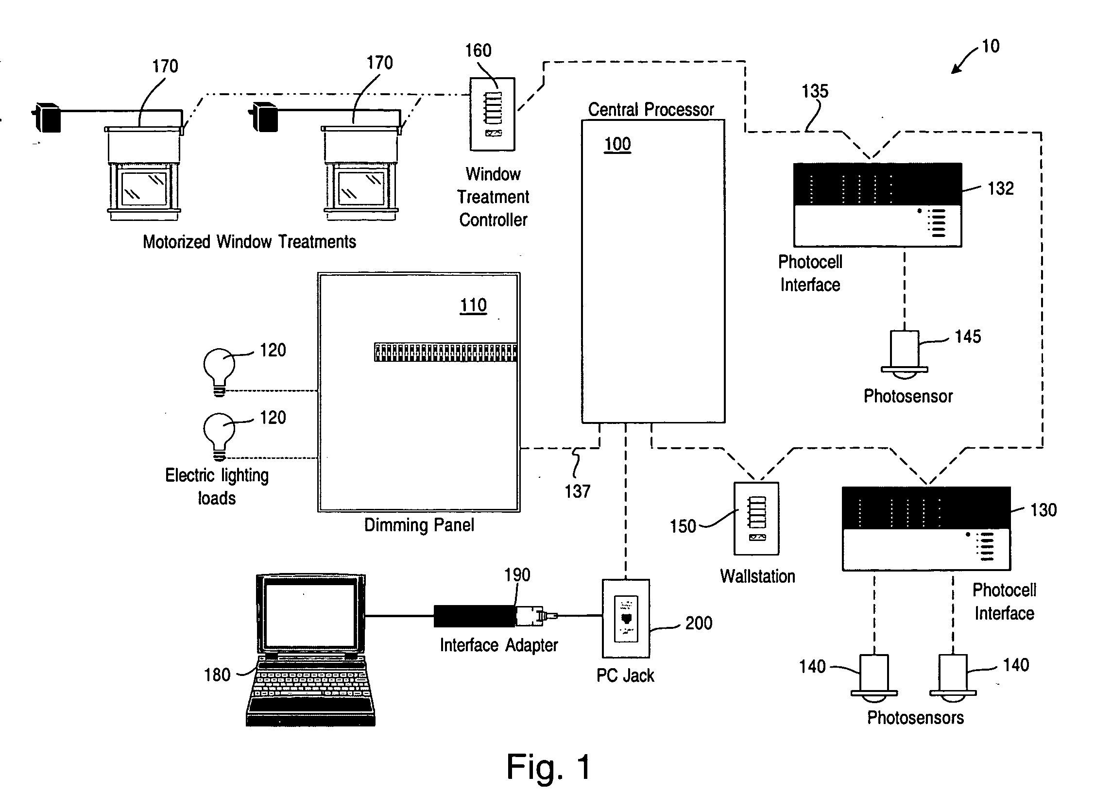
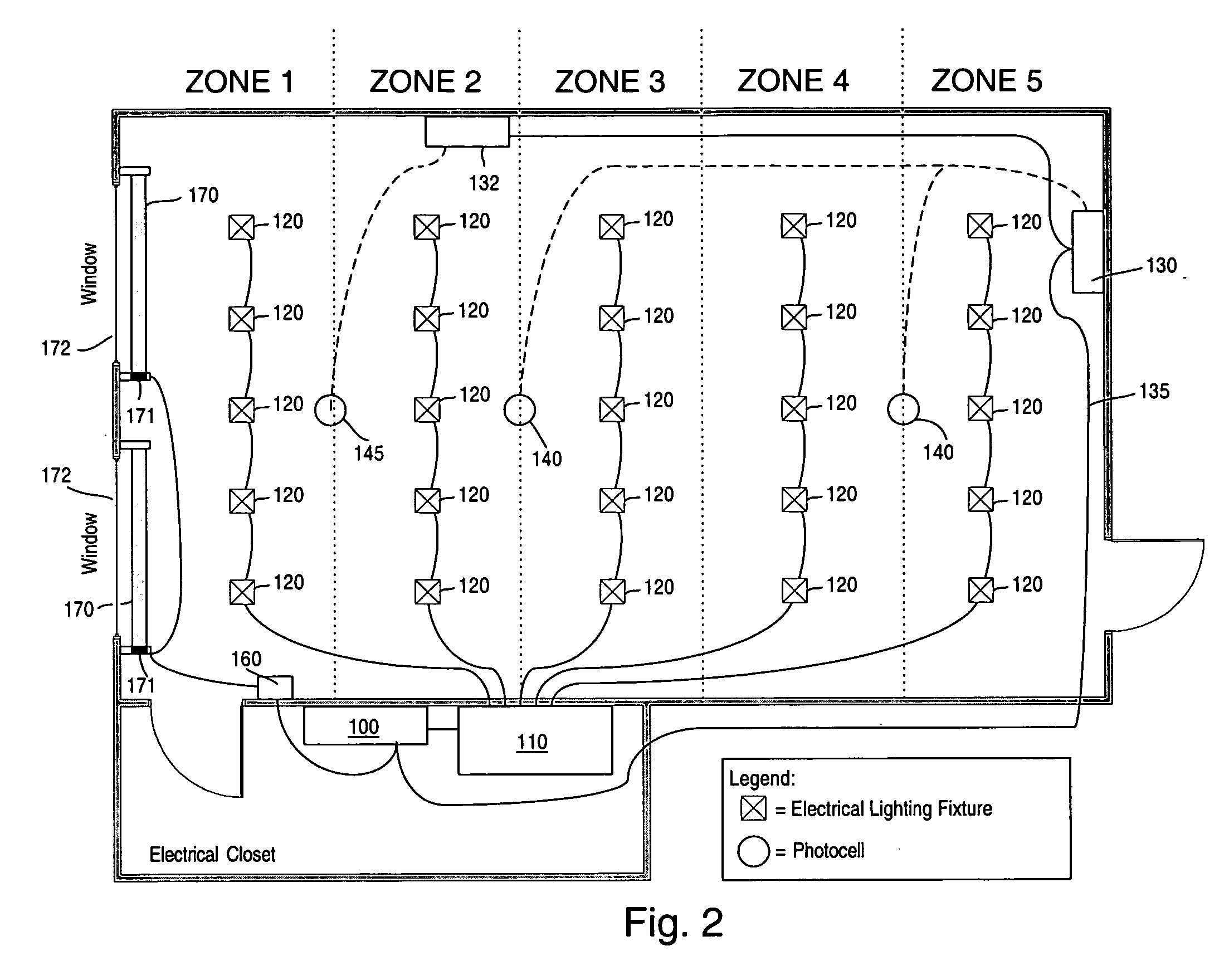
[0056] With reference now to the drawings, FIG. 1 is a block diagram of an embodiment of the invention for controlling the illumination levels in a space such as a room, where both daylight and artificial lighting act as light sources, as well as for reducing sun glare. The system 10 comprises a central processor 100 which may be a Lutron GRAFIK 6000® central lighting processor, for example, Model No. GR6MXINP. The central processor 100 has coupled thereto a dimming panel 110 which has various lighting loads 120 which can be any light source type including but not limited to incandescent, fluorescent, HID (High Intensity Discharge), neon, LED (Light Emitting Diode), LV (Low Voltage) coupled thereto and which are controlled by the dimming panel 110 in response to commands from the central processor 100 communicated via a digital communication link 137. The dimming panel may be a Lutron type GP12-1203ML-15. Photosensor interface 130 is coupled to the central processor via a digital co...


PUM


Abstract

An illumination maintenance system for maintaining a desired illumination profile in a space throughout at least a portion of a day where the illumination sources include daylight and artificial light, the system comprising a first sensor for sensing an illumination level in at least a portion of the space, at least one window treatment for at least one opening for allowing daylight into the space, the window treatment selectively altering the amount of daylight entering the space, a plurality of electric lamps providing artificial light to supplement the daylight illumination of the space; the electric lamps being dimmable, a control system controlling the at least one window treatment and the plurality of electric lamps to maintain the desired illumination profile in the space, the control system controlling the plurality of electric lamps so that the dimming level of each lamp is adjusted to achieve the desired lighting profile and compensate for the daylight illumination in the space throughout at least the portion of the day; and the control system further operating to adjust the window treatment in the event of sun glare through the opening to reduce the sun glare and such that when the desired illumination profile within a defined tolerance is achieved, the control system stops varying the dimming levels of the lamps and the adjustment of the at least one window treatment.

Description

CROSS REFERENCE TO RELATED APPLICATIONS [0001] This application claims the benefit and priority of U.S. Provisional application Ser. No. 60 / 457,276 filed Mar. 24, 2003 entitled “Multi-Zone Closed Loop Illumination Maintenance System” and U.S. Provisional application Ser. No. 60 / 529,996 filed Dec. 15, 2003 entitled “System To Control Daylight and Artificial Illumination and Sun Glare in a Space” and is related to U.S. application Ser. No. 10 / 660,061 filed Sep. 11, 2003, entitled “MOTORIZED WINDOW SHADE CONTROL” and U.S. Pat. No. 4,236,101 granted Nov. 25, 1980 entitled “Light Control System” the entire disclosures of which are hereby incorporated by reference herein.BACKGROUND OF THE INVENTION [0002] The present invention relates to a system to provide sufficient and comfortable lighting within a space. In particular, the invention relates to a system for the automatic control of the light levels in a space by the control of the intensity of electric lighting and / or daylight in a spa...

Claims


Application Information

Patent Timeline
Patent Type & Authority Applications(United States)
IPC IPC(8): H05B37/02
CPCE06B9/32E06B9/68H05B37/0209Y10S362/802Y02B20/46Y02B80/50H05B37/0218H05B47/10H05B47/11H05B47/165Y02B20/40Y02B80/00Y02A30/24
Inventor VESKOVIC, DRAGAN
Owner LUTRON TECH CO LLC
Learn More