
Tread having tread pattern elements formed of at least two rubber mixes

Inactive Publication Date: 2005-05-26
MICHELIN RECH & TECH SA
View PDF7 Cites 30 Cited by
  • Summary
  • Abstract
  • Description
  • Claims
  • Application Information

AI Technical Summary

Benefits of technology

[0020] It was mentioned further above that one method of improving the grip performance of a mix on wet ground of a rubber composition may be obtained by increasing the Tg of said composition. This method consists, for example and as is known, of modifying the nature of the polymer and in particular the microstructure thereof (in particular in the case of an SBR by appropriately adjusting either the amount of styrene or the amount of vinyl or both). Preferably, the difference in Tg between the base mix and the covering mix is at least 5° C.
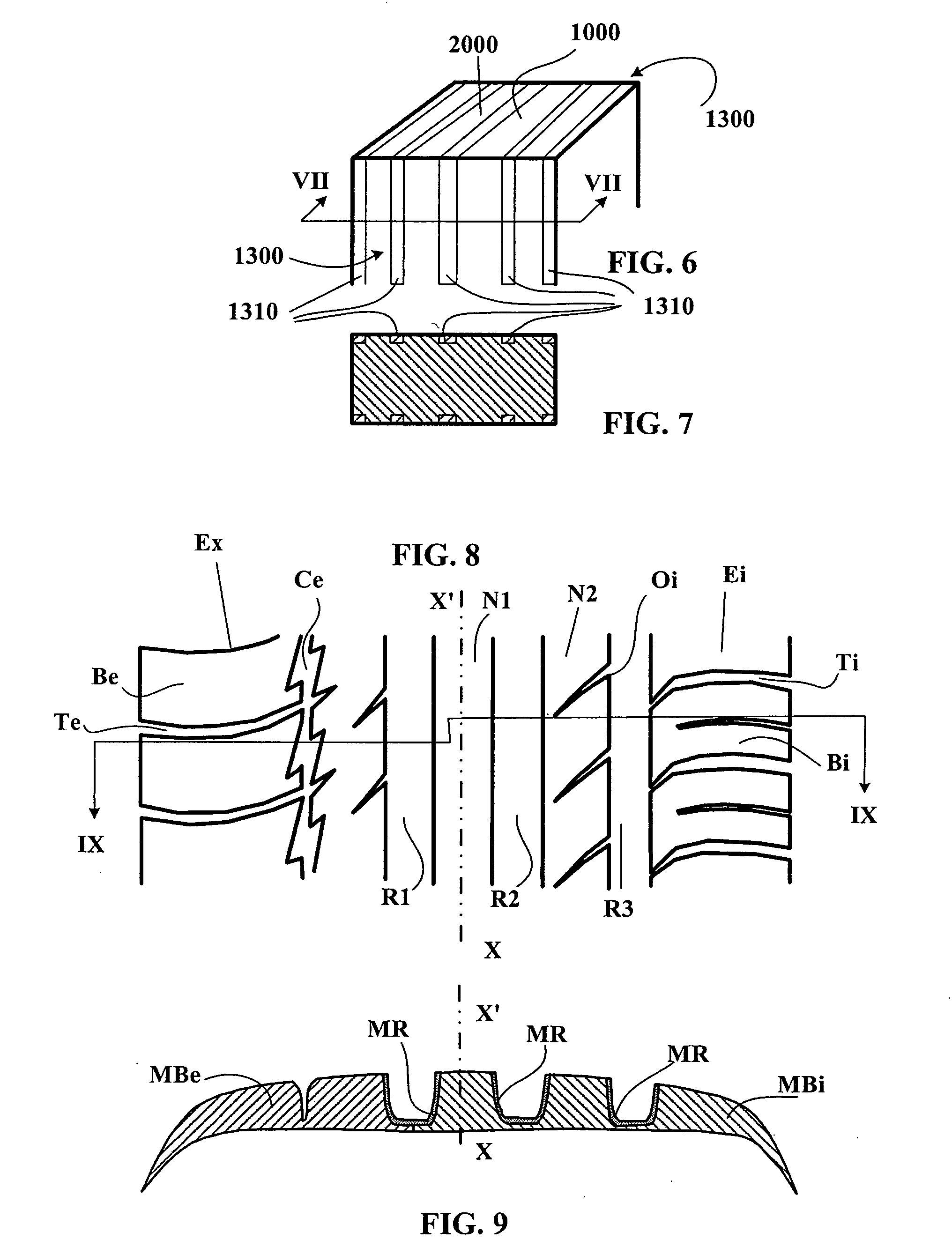
[0026] Advantageously, all the lateral faces of the elements in relief defining circumferential grooves are provided with a covering mix of grip on wet ground which is greater than the grip of the base mix in order to improve very substantially the cornering performance (under transverse stresses) on wet ground. Of course, different covering mixes may be used in combination with a base mix (or even several base mixes); in this case, each covering mix has a grip on wet ground which is better than that of the base mix which is directly adjacent thereto. Advantageously, the elements in relief located towards the inside of a vehicle on which is mounted the tire provided with the tread according to the invention may comprise an internal covering mix and the elements towards the outside may comprise an external covering mix, these covering mixes being of different grip characteristics, the greater grip being, for example, located to the inside relative to the equatorial plane of the tire in order to produce a better compromise between the grip on a dry road and the grip on a damp road.

Problems solved by technology

However, in parallel to this improvement in grip performance on wet ground, a loss of wear performance on a dry road occurs, which results in a reduced wear life and necessitates more frequent changing of the tires on a vehicle.

Method used


Image

  • Tread having tread pattern elements formed of at least two rubber mixes
  • Tread having tread pattern elements formed of at least two rubber mixes
  • Tread having tread pattern elements formed of at least two rubber mixes

Examples


Embodiment Construction

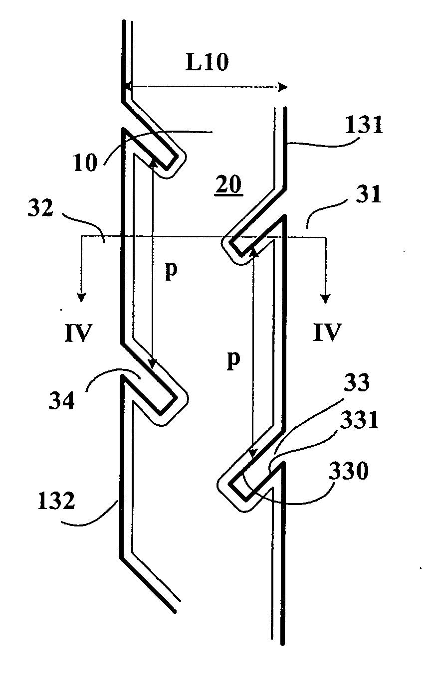
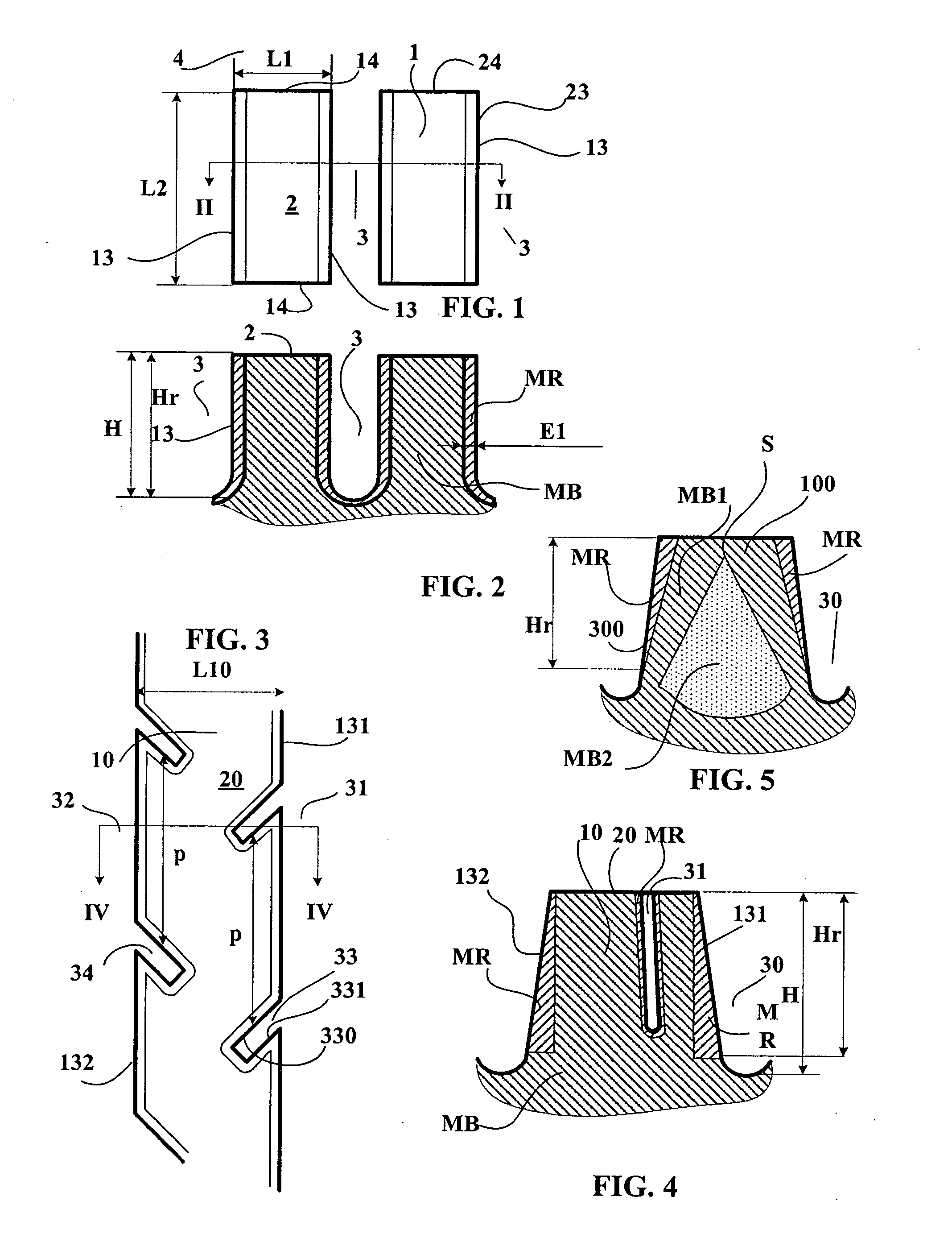
[0041] In FIG. 1, there can be seen the contact faces 2 of two blocks 1 of a tread pattern according to the invention. Each of these blocks 1 comprises four lateral faces 13 and 14 defined respectively by grooves of longitudinal 3 and transverse 4 orientation. The intersections of the lateral faces of each block with its contact face 2 form ridges 23, 24 which play an important part during travel and in particular on a wet road. Each block 1 is rectangular, of width L1 and of length L2 (the direction of the length L1 of the blocks in the case described being the same as the longitudinal direction of the tread or alternatively the circumferential direction on the tire provided with said tread.

[0042] On the cross-section shown in FIG. 2 and taken along the line 11-11 of FIG. 1 and perpendicular to the contact faces 2 of the blocks 1, it can be seen that the faces or lateral faces 13 defining the grooves of longitudinal orientation 3 are covered with a substantially constant thickness...


PUM


Abstract

A tire tread comprising: a plurality of elements in relief (rib and / or block) comprising a contact face intended to come into contact with the roadway during travel and lateral faces, the intersection of each lateral face with the contact face forming a ridge, a plurality of cutouts in the form of grooves and / or incisions, said cutouts being defined by opposing main faces, each tread pattern element being formed with at least one rubber mix (referred to as “base mix”), and characterized in that, viewed in section in a plane containing the thickness of this tread, at least one face defining at least one cutout is formed at least in part with a rubber mix, referred to as “covering mix”, the base mix having a grip on wet ground which is lower than the grip of the covering mix on the same ground.

Description

FIELD OF INVENTION [0001] The invention relates to tires and more particularly to the treads of such tires. BACKGROUND OF INVENTION [0002] In order to obtain satisfactory performance during travel in particular on a wet road, it is known to provide a tread of a tire with a tread pattern formed by tread pattern elements which are separated from each other by cutouts (grooves of average width greater than or equal to 2.5 mm and incisions of average width less than 2.5 mm), these cutouts being obtained for example by molding. The tread pattern elements thus formed comprise a contact face intended to come into contact with the roadway during travel and lateral faces also defining the cutouts; the intersection of each lateral face with the contact face forms a ridge which facilitates the contact of the tire with the roadway, and in particular when the latter is wet. More generally, a ridge is defined as the geometric limit of contact of a tread pattern element with the ground during trav...

Claims


Application Information

Patent Timeline
IPC IPC(8): B60C5/00B60C11/00B60C11/03B60C11/04B60C11/11B60C11/18B60C19/00
CPCB60C11/00B60C11/0306B60C11/18B60C11/005B60C11/0304B60C11/1346B60C11/0058B60C19/001
Inventor BRUANT, REMIVASSEUR, DIDIER
Owner MICHELIN RECH & TECH SA
Learn More