Rapid thermal chemical vapor deposition apparatus and method

Inactive Publication Date: 2005-05-26
CHEN XIANGQUN S +1
View PDF4 Cites 36 Cited by
  • Summary
  • Abstract
  • Description
  • Claims
  • Application Information

AI Technical Summary

Benefits of technology

[0026] According to a another aspect of the preferred embodiment, a temperature regulation chuck supports the substrate. In this case, the chuck cools the substrate so as to prevent damage thereto.
[0032] According to a yet another aspect of the preferred embodiment, a carbon nanotube fabrication system having a chamber that supports a substrate includes a high intensity thermal radiation source for heating the chamber, and a temperature regulation chuck that supports the substrate. In this embodiment, the chuck cools the substrate so as to prevent damage to the substrate during formation of the carbon nanotubes.

Problems solved by technology

Also, this goal can be further achieved by controlling gas flow and gas distribution in a non-uniform fashion, with or without the aforementioned temperature control.

Method used


Image

  • Rapid thermal chemical vapor deposition apparatus and method
  • Rapid thermal chemical vapor deposition apparatus and method
  • Rapid thermal chemical vapor deposition apparatus and method

Examples


Embodiment Construction

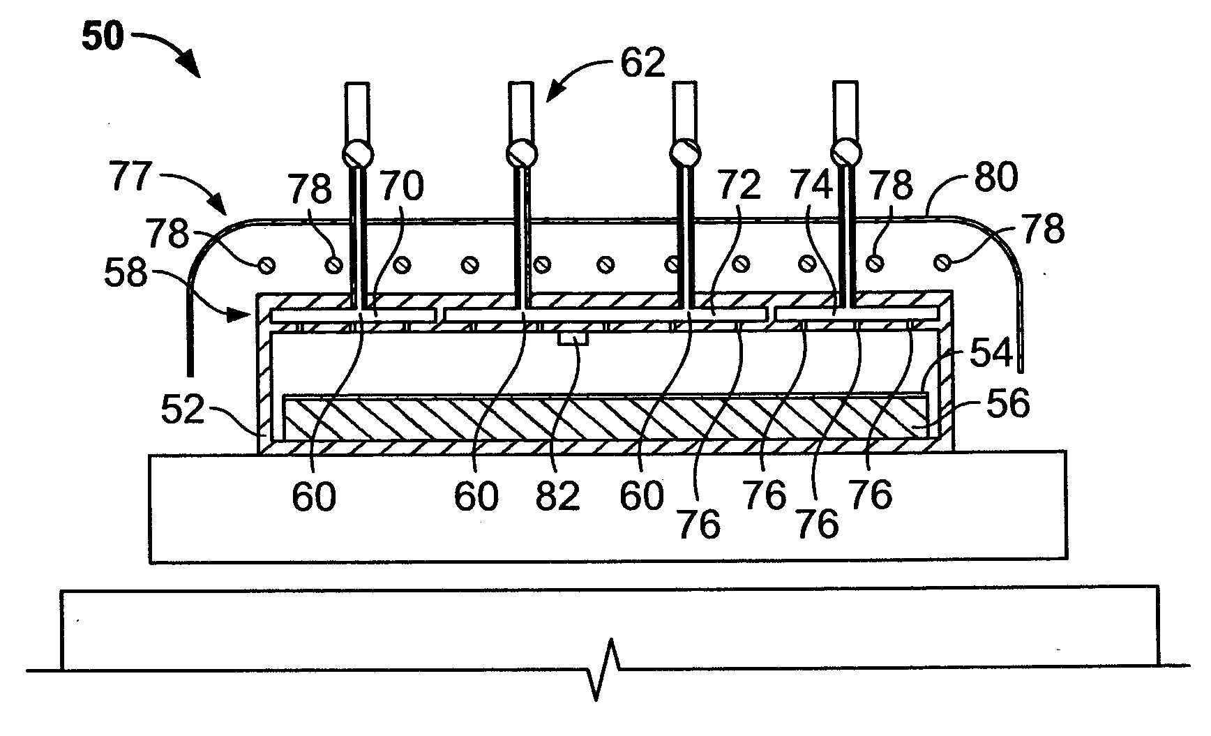
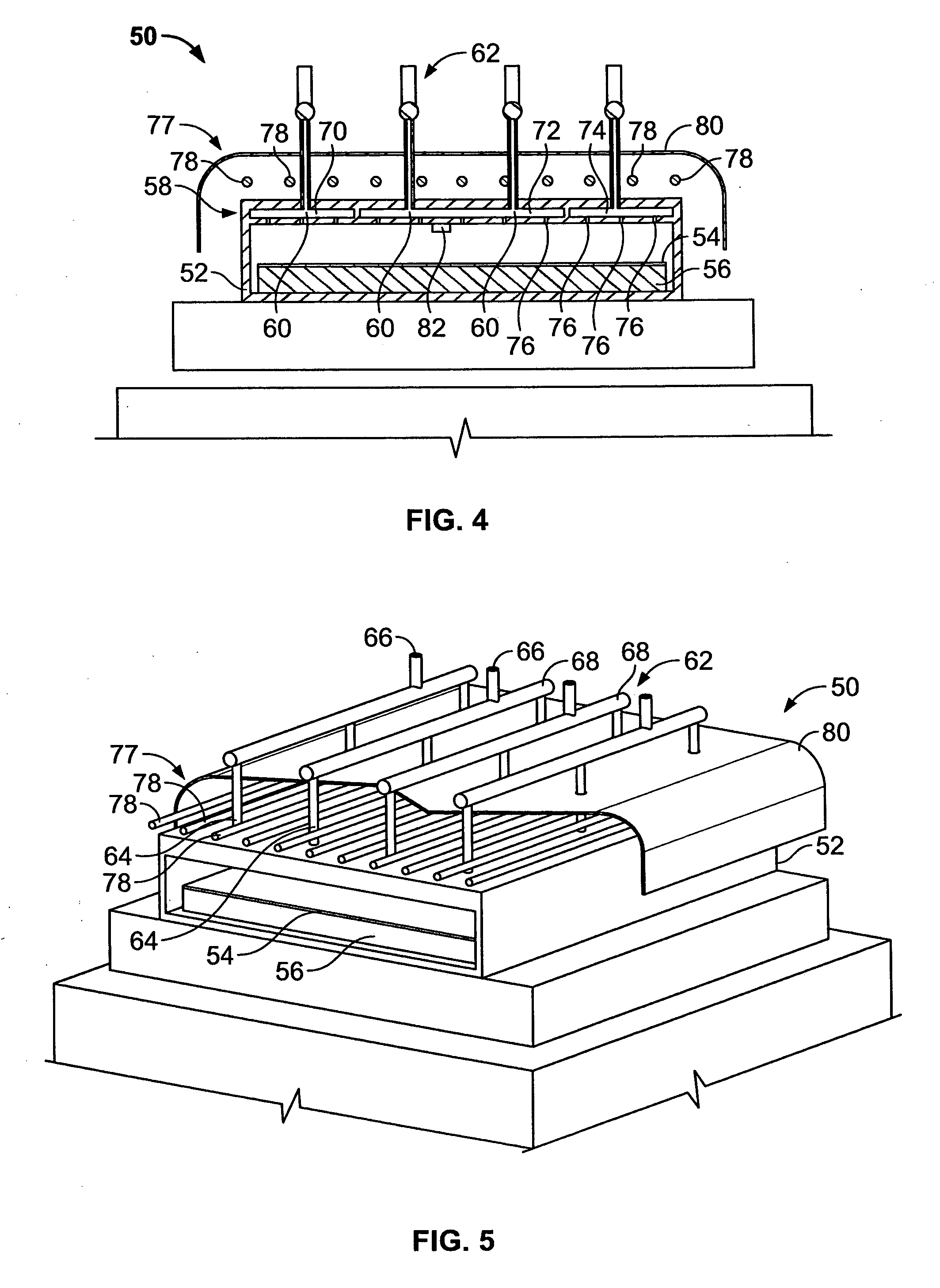
[0047] Turning initially to FIGS. 4 and 5, a rapid thermal CVD carbon nanotube fabrication apparatus 50 includes a chamber 52, preferably made of quartz, having a rectangular cross-section designed to accommodate a substrate 54, for example a flat, rectangular glass substrate for a field emission display application. The dimensions of chamber 52 are not intended to limit the scope of the preferred embodiment, they are only schematically illustrated for purposes of example only. Substrate 54 is supported by a temperature regulated chuck 56, the function of which will be apparent from the discussion below.

[0048] The quartz chamber 52 preferably includes a multi-zone showerhead 58 that includes a plurality of openings 60 coupled to a gas delivery system 62 for receiving gas from any number of gas sources (not shown). More specifically, gas delivery system 62 includes a plurality of pipes 64, 66, 68 coupled to chamber 52, and specifically, showerhead 58.

[0049] Showerhead 58 preferably...


PUM

PropertyMeasurementUnit
Timeaaaaaaaaaa
Temperatureaaaaaaaaaa
Timeaaaaaaaaaa

Abstract

A carbon nanotube fabricating system and method that includes a process chamber that supports a substrate. The system employs a high intensity thermal radiation source for heating the chamber, and a temperature regulation chuck that supports the substrate. In process, the chuck cools the substrate so as to prevent damage to the substrate, while CNT fabrication is preferably regulated to occur in a process window.

Description

CROSS REFERENCE TO RELATED APPLICATION [0001] This application is a non-provisional application based on a provisional application Ser. No. 60 / 505,360 filed on Sep. 22, 2003, the entirety of which is expressly incorporated by reference herein.BACKGROUND OF THE INVENTION [0002] 1. Field of the Invention [0003] The present invention is directed to a chemical vapor deposition (CVD) system and corresponding method, and more particularly, a CVD system and method for carbon nanotube synthesis on a substrate using an apparatus employing a rapid thermal process. [0004] 2. Description of Related Art [0005] Since their discovery over a decade ago, carbon nanotubes have shown great promise in a wide variety of technologies, including extending Moore's Law beyond the physical limitations of known silicon techniques. Carbon nanotubes are much like elongated bucky balls, a form of carbon-composed clusters of approximately 60 carbon atoms, bonded together in an apolyhedral, or many-cited structure...

Claims


Application Information

Patent Timeline
IPC IPC(8): C01B31/02C23C16/00C23C16/455C23C16/48C23C16/52D01F9/127D01F9/133
CPCB82Y30/00B82Y40/00C01B31/0233D01F9/133C23C16/482C23C16/52D01F9/127C23C16/45565C01B32/162
Inventor CHEN, XIANGQUN S.ADDERTON, DENNIS M.
Owner CHEN XIANGQUN S
Why Eureka
Try Eureka