
Cluster failover from physical node to virtual node

a cluster and virtual node technology, applied in the field of information handling systems, can solve the problems of not being able to host applications, not being able to solve the problem of n+n mechanism, not being able to solve the problem of a viable option, and being very expensiv

Inactive Publication Date: 2005-05-19
DELL PROD LP
View PDF16 Cites 165 Cited by
  • Summary
  • Abstract
  • Description
  • Claims
  • Application Information

AI Technical Summary

Benefits of technology

[0014] The use of virtual nodes for failover purposes preserves the segregation of applications for compatibility and security reasons. Moreover, the failover virtual nodes can be distributed among several physical nodes so that any particular node is not overly impacted if multiple failures occur. Finally, the failover technique of the present invention can be combined with other failover techniques, such as N+1, so that the failover can be directed to virtual failover nodes on the backup server to further enhance failover redundancy and capacity. The present invention, therefore, is ideal for mission critical applications that cannot be run simultaneously on a single node.
[0018] The present invention also provides a system comprising a cluster. The cluster is composed of one or more cluster nodes, with each of the cluster nodes being constructed and arranged to execute one or more processes. A distributed cluster manager is provided that is operative with each of said cluster nodes. The distributed cluster manager is constructed and arranged to detect one or more failures of one or more processes on any of the cluster nodes. Finally, the system is provided with a second (failover) server. The second server is operative with the distributed cluster manager. The second server has a dynamic virtual failover layer that is operative with the distributed cluster manager. In addition, the second server has one or more virtual nodes that are operative with the dynamic virtual failover layer. Each of the virtual nodes of the second server is constructed and arranged to execute said one or more processes of the cluster nodes. If one or more of the cluster nodes fails, then one or more processes of the failed cluster node are transferred to one or more of the virtual nodes of the second server. A third (or more) servers can also be added to the system preferably having the same capabilities as the second server. When two additional servers are operative with the cluster, one of the servers can be the failover server, and the other one the backup server. As mentioned before, additional servers may be added to the cluster to provide additional virtual machines (nodes) to further enhance the robustness and availability of the processes of the system.

Problems solved by technology

However, if more than one physical node fails, N+1 mechanism cannot host the applications from the multiple servers since the applications are incompatible.
While an N+N failover mechanism is the ideal solution in such a scenario, the N+N mechanism is very expensive and not a viable option for economic reasons.

Method used


Image

  • Cluster failover from physical node to virtual node
  • Cluster failover from physical node to virtual node
  • Cluster failover from physical node to virtual node

Examples


first embodiment

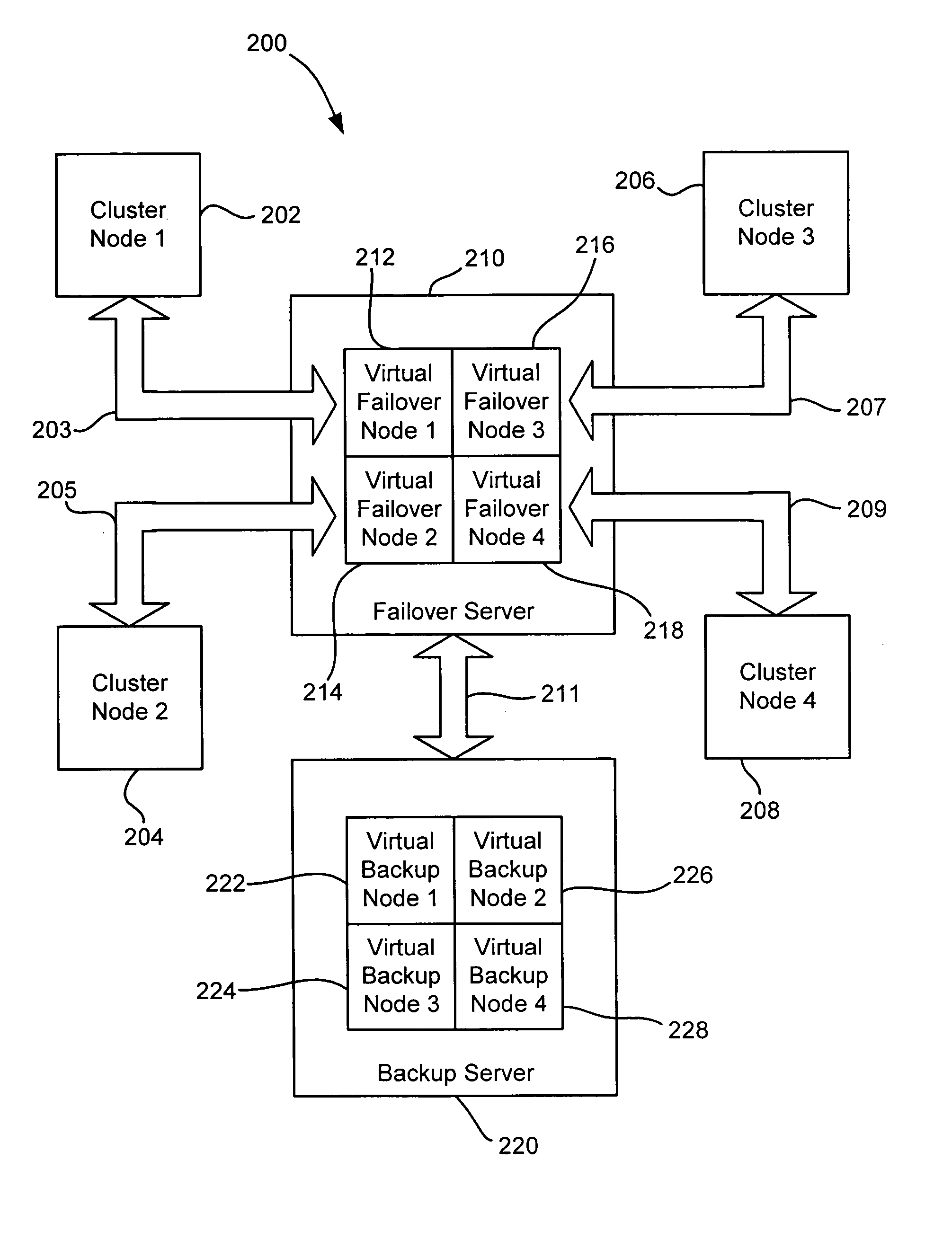
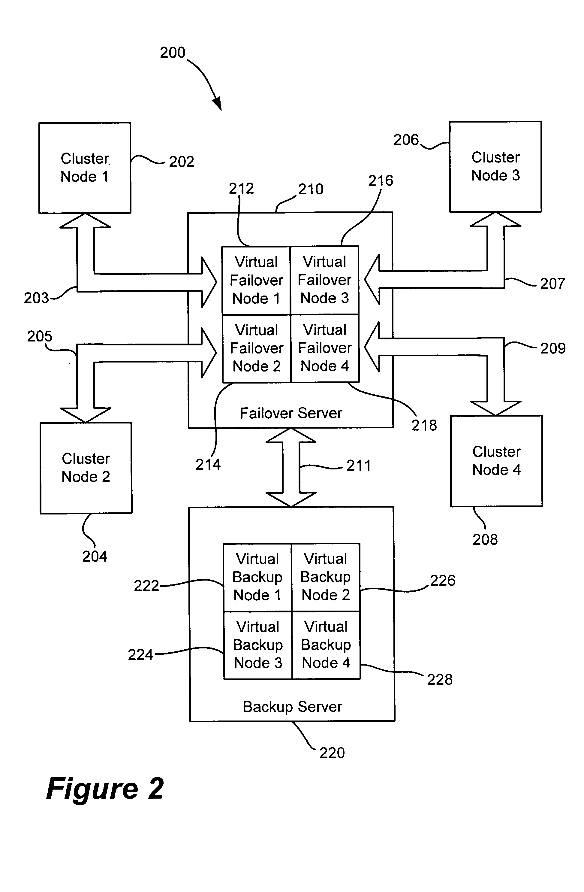
[0035] the present invention is illustrated in FIG. 2. The system 200 has four nodes in the cluster, specifically nodes 202, 204, 206, and 208. While four nodes are shown, it will be understood that clusters of greater and lesser nodes can be used with the present invention. In addition to the nodes 202-208, which in this example are physical nodes, there is also a failover server 210 and a backup server 220, as illustrated in FIG. 2. The failover server 210 is equipped with four virtual failover nodes 212, 214, 216, and 218 that correspond to cluster nodes 202, 204, 206, and 208, respectively, through data channels 203, 205, 207, and 209, respectively. While multiple data channels are shown in this embodiment, it will be understood that a single data channel (akin to a data bus) could be used to convey the failover and service the data communication traffic. The backup server 220 is operative with the failover server 210 via data channel 211 as illustrated in FIG. 2. As with the fa...

second embodiment

[0036]FIG. 3 illustrates the present invention. The system 300 has multiple cluster nodes 302, 304, 306, and 308 that are constructed and arranged to communicate with a distributed cluster manager 310 through messages 303, 305, 307, and 309, respectively. The distributed cluster manager 310 can communicate through messages 311 and 315 to the failover server 312 and to the backup server 322, respectively, as illustrated in FIG. 3. Further, the failover server 312 can communicate with the backup server 322 through messages 313. The failover server 312 is equipped with a dynamic virtual failover layer 314 that receives the messages 311 from the distributed cluster manager 310. The dynamic virtual failover layer 314 governs the activities of the multiple virtual nodes 316, 318 and others (not shown) of the failover server 314. While two virtual nodes are shown in the failover server 312, it will be understood that one or more virtual nodes (virtual machines) may be implemented on the fa...


PUM


Abstract

The present invention provides a system, method and apparatus for facilitating the failover of a cluster process from a physical node to a virtual node so that interrupts of the affected software application are minimized. Upon detection that a node on the cluster has failed, a signal is sent to the failover or the backup server to start a virtual machine (virtual node) that can accommodate the failed process. The failed process is then resumed on the virtual node until the failed node is rebooted, repaired, or replaced. Once the failed node is made operational, the process that is running on the virtual node is transferred back to the newly operational node.

Description

BACKGROUND OF THE INVENTION TECHNOLOGY [0001] 1. Field of the Invention [0002] The present invention is related to information handling systems, and more specifically, to a system and method for providing backup server service in a multi-computer environment in the event of failure of one of the computers. [0003] 2. Description of the Related Art [0004] As the value and the use of information continue to increase, individuals and businesses seek additional ways to process and store information. One option available to users is information handling systems. An information handling system generally processes, compiles, stores and / or communicates information or data for business, personal or other purposes, thereby allowing users to take advantage of the value of the information. Because technology and information handling needs and requirements vary between different users or applications, information handling systems may also vary regarding what information is handled, how the inform...

Claims


Application Information

Patent Timeline
IPC IPC(8): G06F11/00G06F15/177
CPCG06F11/2028G06F11/1484G06F2201/815
Inventor PURUSHOTHAMAN, RANJITHNAJAFIRAD, PEYMAN
Owner DELL PROD LP
Learn More