
Method of transferring large uncured composite laminates

a composite laminate and large-scale technology, applied in the direction of manufacturing tools, transportation and packaging, efficient propulsion technologies, etc., can solve the problems of increasing cost, reducing fabrication efficiency, and not providing an interference-free means for automated processes to lay multiple parts, so as to achieve the effect of reducing manufacturing efficiency, low capital equipment investment, and smoothness

Inactive Publication Date: 2005-05-19
THE BOEING CO
View PDF43 Cites 64 Cited by
  • Summary
  • Abstract
  • Description
  • Claims
  • Application Information

AI Technical Summary

Benefits of technology

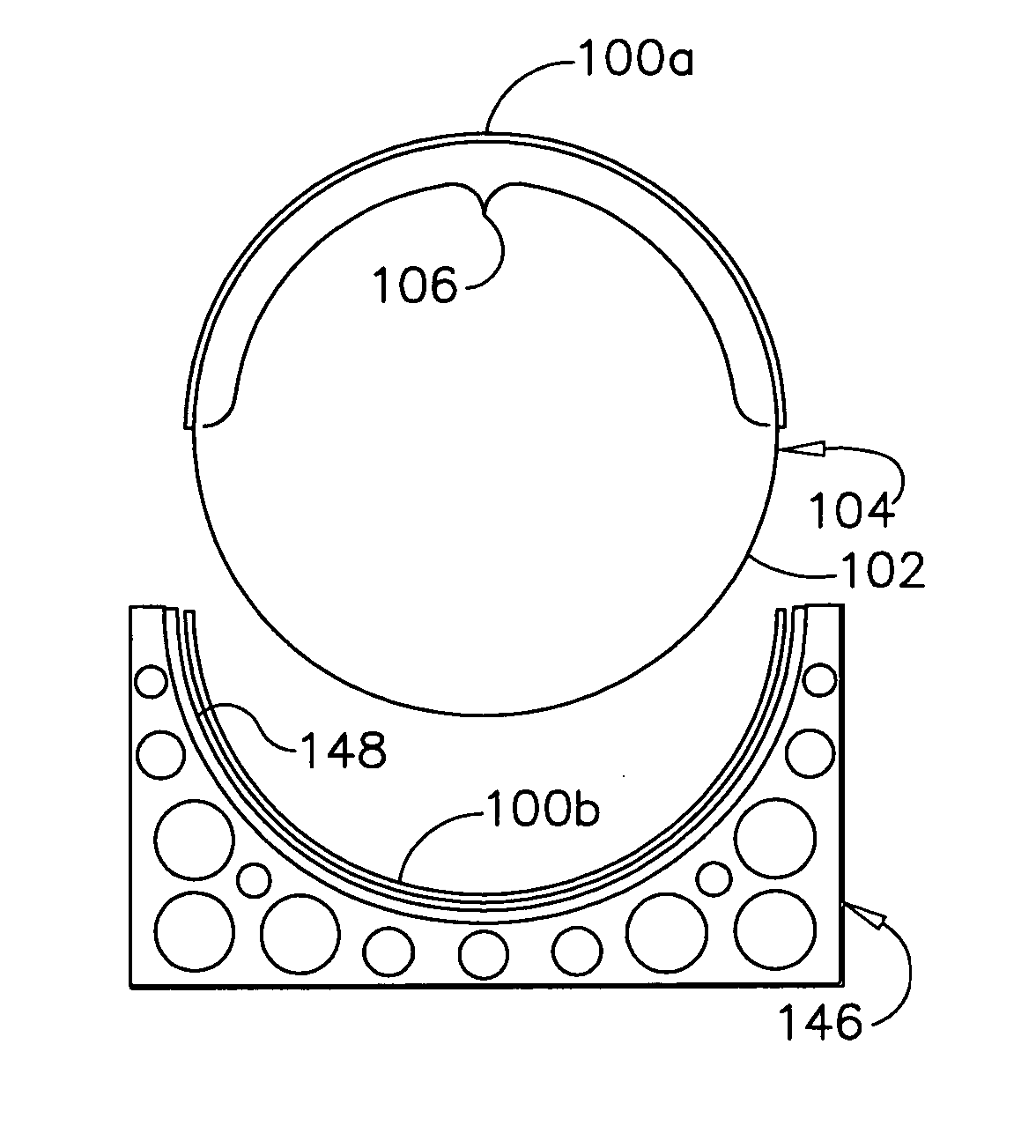
[0010] Transferring skins fabricated on a male lay-up mandrel to a female cure tool can provide both the desired aero-smoothness and a low capital equipment investment. Such a method cuts the skins into sections, separates the uncured laminate from the lay-up tool, and transfers the uncured laminate sections to an outer mold line cure tool. For fuselage skins, it would be far more efficient to lay up an entire barrel section than to build smaller panels and join them during assembly. Placing the composite material directly on the inside of a large cylindrical tool to provide lay up directly to the aero surface, however, presents certain challenges that are not encountered in placing composite material on the outside of a tool, which is a more mature technology.

Problems solved by technology

Placing the composite material directly on the inside of a large cylindrical tool to provide lay up directly to the aero surface, however, presents certain challenges that are not encountered in placing composite material on the outside of a tool, which is a more mature technology.
Although it is common practice to place laminates on top of vacuum bag surfaces, or other transfer medium, to take advantage of automated lay-up methods, and to provide an easy means of transfer of the uncured part to the cure tool, these methods apply only to single parts and do not provide an interference free means for automated processes to lay-up multiple parts across adjacent and independent transfer zones.
Interrupting the lay-up in the circumferential direction, for example, by providing a built-in seam, or making the lay-up discontinuous in the circumferential direction, in favor of a particular method for transferring skins would decrease fabrication efficiency and increase cost.
Moreover, such approaches would interfere with the lay-up of the skin.
For example, bumps in the lay-up surface in the vicinity of such an interruption or discontinuity can cause problems with bridging of the material over the bump and interfere with the material delivery head that passes over the bump.

Method used


Image

  • Method of transferring large uncured composite laminates
  • Method of transferring large uncured composite laminates
  • Method of transferring large uncured composite laminates

Examples


Embodiment Construction

[0033] The following detailed description is of the best currently contemplated modes of carrying out the invention. The description is not to be taken in a limiting sense, but is made merely for the purpose of illustrating the general principles of the invention, since the scope of the invention is best defined by the appended claims.

[0034] The Boeing Company is exploring a variety of methods and tools for making large composite structures. The present application describes an invention that is one of a family of inventions for accomplishing this goal The present application is related to the following co-pending U.S. patent applications that are part of this family: U.S. patent application Ser. No. 10 / 646,509, entitled “Multiple Head Automated Composite Laminating Machine For The Fabrication Of Large Barrel Section Components”, filed Aug. 22, 2003; U.S. patent application Ser. No. 10 / 646,392, entitled “Automated Composite Lay-Up To An Internal Fuselage Mandrel”, filed Aug. 22, 20...


PUM

PropertyMeasurementUnit
diameteraaaaaaaaaa
compaction pressuresaaaaaaaaaa
diameteraaaaaaaaaa

Abstract

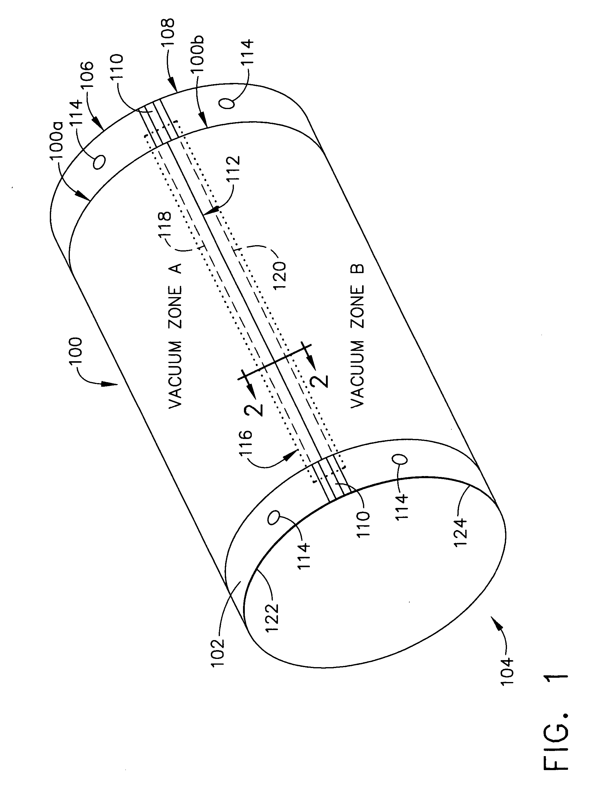
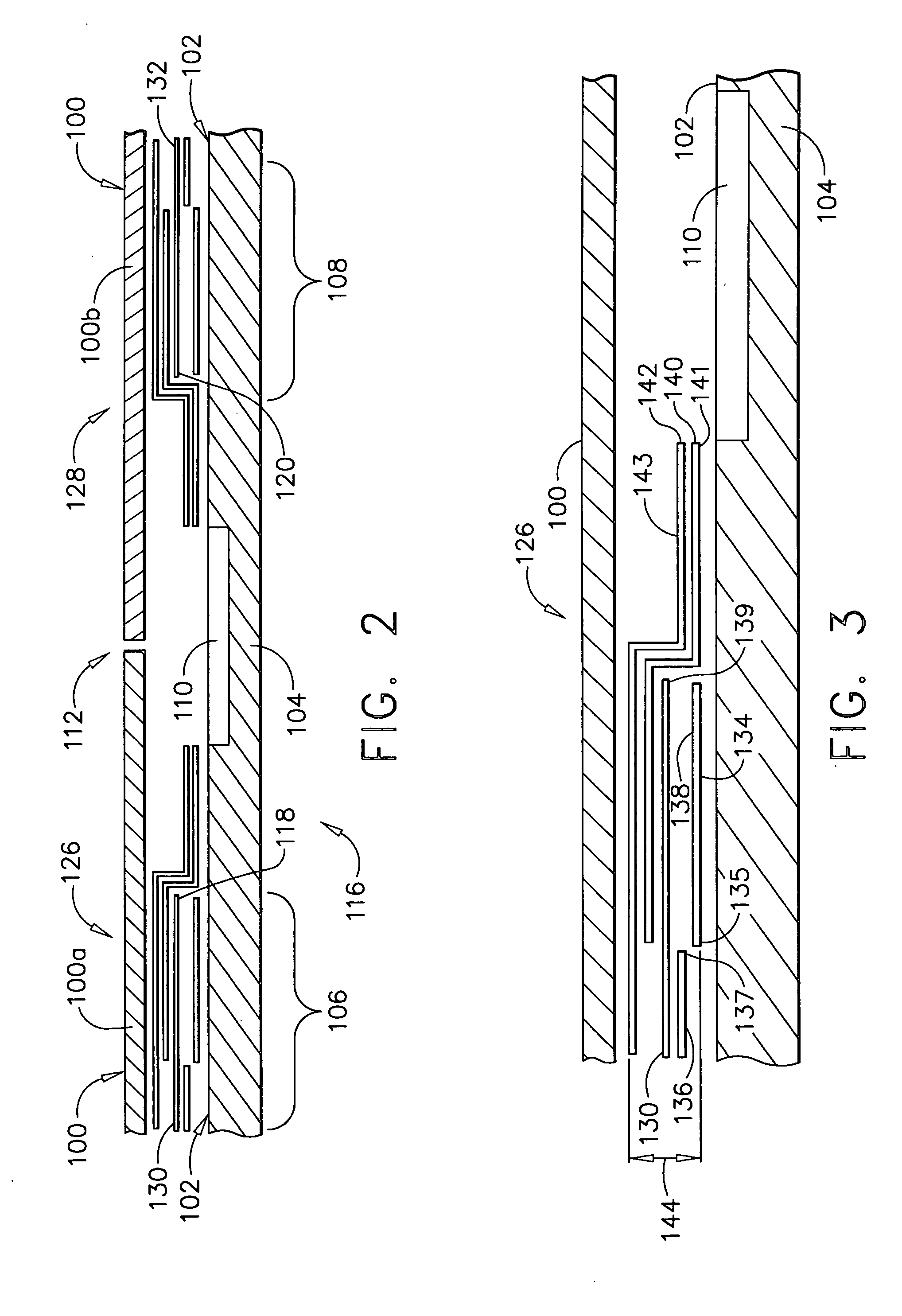
A method of transferring an uncured composite laminate skin from a lay-up surface of a male mandrel tool to a female cure tool includes defining multiple vacuum zones on the lay-up surface, each zone corresponding to one of a multiple of portions into which the skin is to be separated. For example, to separate the skin into two portions, a low profile seal of a first membrane to the lay-up surface is formed at a first vacuum zone and a second low profile seal for a second membrane is formed at a second vacuum zone. The method further includes laying up a composite laminate skin over all the vacuum zones; separating the composite laminate skin into portions, for example, a first portion over the first vacuum zone and a second portion over the second vacuum zone; and releasing the portions individually into cure tools having an outside mold line surface.

Description

CROSS REFERENCE TO RELATED APPLICATIONS [0001] The present application is related to the following co-pending U.S. patent applications: U.S. patent application Ser. No. 10 / 646,509, filed Aug. 22, 2003; U.S. patent application Ser. No. 10 / 646,392, filed Aug. 22, 2003; U.S. patent application Ser. No. 10 / 630,594, filed Jul. 28, 2003; U.S. patent application Ser. No. 10 / 646,316, filed Aug. 22, 2003; and U.S. patent application Ser. No. 10 / 301,949, filed Nov. 22, 2002.BACKGROUND OF THE INVENTION [0002] The present invention generally relates to manufacturing of large-scale structures using composite materials and, more particularly, to a method of transferring large uncured composite laminates for the manufacture of large aircraft fuselage sections. [0003] The structural performance advantages of composites, such as carbon fiber epoxy and graphite bismaleimide (BMI) materials, are widely known in the aerospace industry. Aircraft designers have been attracted to composites because of the...

Claims


Application Information

Patent Timeline
Patent Type & Authority Applications(United States)
IPC IPC(8): B29C33/68B29C37/00B29C53/60B29C53/68B29C69/00B29C70/30B29C70/44B29C70/54
CPCB29C33/68B29C37/0003B29C53/60B29C53/68B29C70/30Y10T29/49867B29C70/543Y02T50/433Y10T29/49998Y10T29/49895Y10T29/49879B29C70/446Y02T50/40
Inventor ANDERSON, DONALD A.JOHNSON, BRICE A.SPOON, STEPHEN S.
Owner THE BOEING CO
Learn More