
Internal combustion engine and connecting rod therefor

a technology of connecting rods and internal combustion engines, which is applied in the direction of connecting rod bearings, machines/engines, crankshafts, etc., can solve the problems of large volume and inability to achieve synergetic effects, and achieve the effects of reducing the overall weight of the main moving parts, and easy to make the crankshaft ligh

Inactive Publication Date: 2005-05-12
HONDA MOTOR CO LTD
View PDF22 Cites 12 Cited by
  • Summary
  • Abstract
  • Description
  • Claims
  • Application Information

AI Technical Summary

Benefits of technology

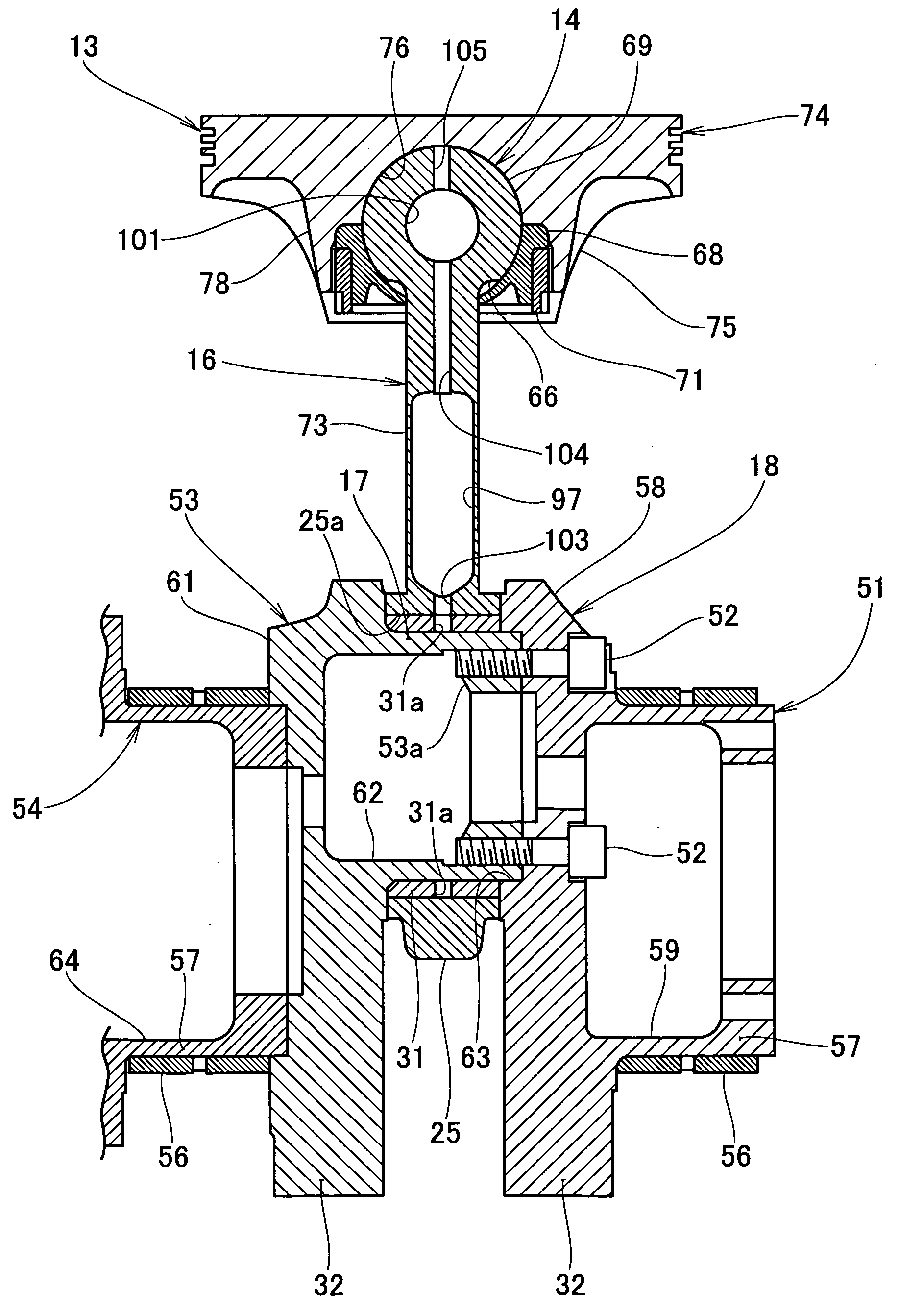
[0014] In this internal combustion engine, by the piston-side joint part of the piston and the spherical small end part of the connecting rod forming a spherical joint, compared to a construction wherein a pair of pin bosses is provided on the piston and the small end of the connecting rod is connected to these pin bosses by a piston pin as in related art, in this invention, the piston pin becomes unnecessary, and if a construction is adopted wherein a concave spherical surface is formed on the piston-side joint part of the piston and a spherical small end part of the connecting rod is fitted in this concave spherical surface, the shapes of the piston and the connecting rod become simple and the piston itself and the respective connecting parts of the piston and the connecting rod can be made light.
[0034] In this invention, preferably, the rod part and the big end part are provided with hollow parts. With this connecting rod for an internal combustion engine, because hollow parts are provided in the rod part and the big end part, the connecting rod can be made light, and in combination with making the assembly-type crankshaft light it is possible to reduce the overall weight of the main moving parts of an internal combustion engine and it is possible to achieve higher speed of the internal combustion engine.

Problems solved by technology

Thus, to reduce the weight of an internal combustion engine, for example to raise the speed, the output and the durability of the internal combustion engine, it is important to reduce the weights of the main moving parts, and if weight-reduction of the main moving parts is not carried out comprehensively, a large, synergetic effect cannot be obtained.

Method used


Image

  • Internal combustion engine and connecting rod therefor
  • Internal combustion engine and connecting rod therefor
  • Internal combustion engine and connecting rod therefor

Examples


Embodiment Construction

[0048] Referring to FIG. 1, an internal combustion engine 10 has a cylinder block 11, a piston 13 fitted movably in a cylinder bore 12 provided in the cylinder block 11, a connecting rod 16 connected to the piston 13 by a spherical joint 14, and a crankshaft 18 rotatably mounted at the bottom of the cylinder block 11 and swingably supporting the connecting rod 16 with a hollow crank pin 17.

[0049] The cylinder block 11 is made up of a cylinder part 21 provided at its top, a cylindrical sleeve 22 fitted inside the cylinder part 21 and forming the cylinder bore 12, and an upper crankcase 23 attached to the bottom of the cylinder part 21.

[0050] Here, reference numeral 31 denotes an integral, seamless float bearing interposed between the a big end 25 of the connecting rod 16 and the crank pin 17; 32 a counterweight provided on the crankshaft 18; 33 a cylinder head mounted on the top of the cylinder block 11 by way of a head gasket (not shown); 34 an intake valve; 36 an exhaust valve; 3...


PUM


Abstract

A connecting rod of an internal combustion engine, and an internal combustion engine including the connecting rod, a piston, a crankshaft and a float bearing as main moving parts. A piston is connected to a connecting rod by a spherical joint and has radial ribs on a rear face of a crown part; a connecting rod is of an integrated, one-piece type having integrally a spherical small end part to be connected to the piston and an annular big end part; the crankshaft is of an assembly type, and a float bearing is interposed between the big end part and a crank pin.

Description

FIELD OF THE INVENTION [0001] This invention relates to an internal combustion engine including a piston, a connecting rod, a crankshaft and a float bearing as main moving parts, and to the detail of a connecting rod for an internal combustion engine. BACKGROUND OF THE INVENTION [0002] An internal combustion engine of related art in which a connecting rod with an integral big end part is connected to an assembly-type crankshaft appears for example in JP-A-6-280847. [0003] A connecting rod for an internal combustion engine of related art that is connected to a piston by a spherical joint appears for example in JP-A-9-144879. The content of JP-A-9-144879 will be explained with reference to FIG. 12. [0004] A crankshaft shown in JP-A-6-280847 is an assembled member made up of a first section, a second section, a third section and a fourth section; a recess is provided in each of a first crank web mounted on the first section and a second crank web mounted on the second section, and a pi...

Claims


Application Information

Patent Timeline
IPC IPC(8): F01M1/06F02F3/00F16C3/12F16C7/02F16C9/04F16C11/06F16C17/18F16J1/22F16J7/00
CPCF01M2001/062F01M2001/066F02F3/0076F16C3/12F16J7/00F16C11/069F16C17/18F16J1/22F16C9/04F16C2360/22
Inventor ENDOH, TSUNEOISHIMITSU, KENGOINOUE, TSUTOMUTSUBOI, TAKAO
Owner HONDA MOTOR CO LTD
Learn More