
Encapsulated composite electrostatic loudspeaker stator

a composite electrostatic and loudspeaker technology, applied in the direction of electrostatic transducer loudspeakers, printed circuit aspects, circuit electrical arrangements, etc., can solve the problems of large problem, failure to use coatings, and obtain the required perforations, etc., to increase the efficiency of electrostatic loudspeakers, high level of precision, and accurate cutting of slots

Inactive Publication Date: 2005-05-05
BLOODWORTH CHARLES P +1
View PDF0 Cites 8 Cited by
  • Summary
  • Abstract
  • Description
  • Claims
  • Application Information

AI Technical Summary

Benefits of technology

[0022] The slots in the stator must be precisely located, and must not expose any of the conductor, as this would negate the benefits of encapsulation. While there are many ways to cut slots accurately, one excellent solution to this problem is the use of computer-controlled routing machines. These are now so accurate that they can reliably produce circuit boards with insulation thickness of only a few microns between the edges of the perforations and the encapsulated copper traces. This high level of precision further increases the efficiency of the electrostatic loudspeaker.
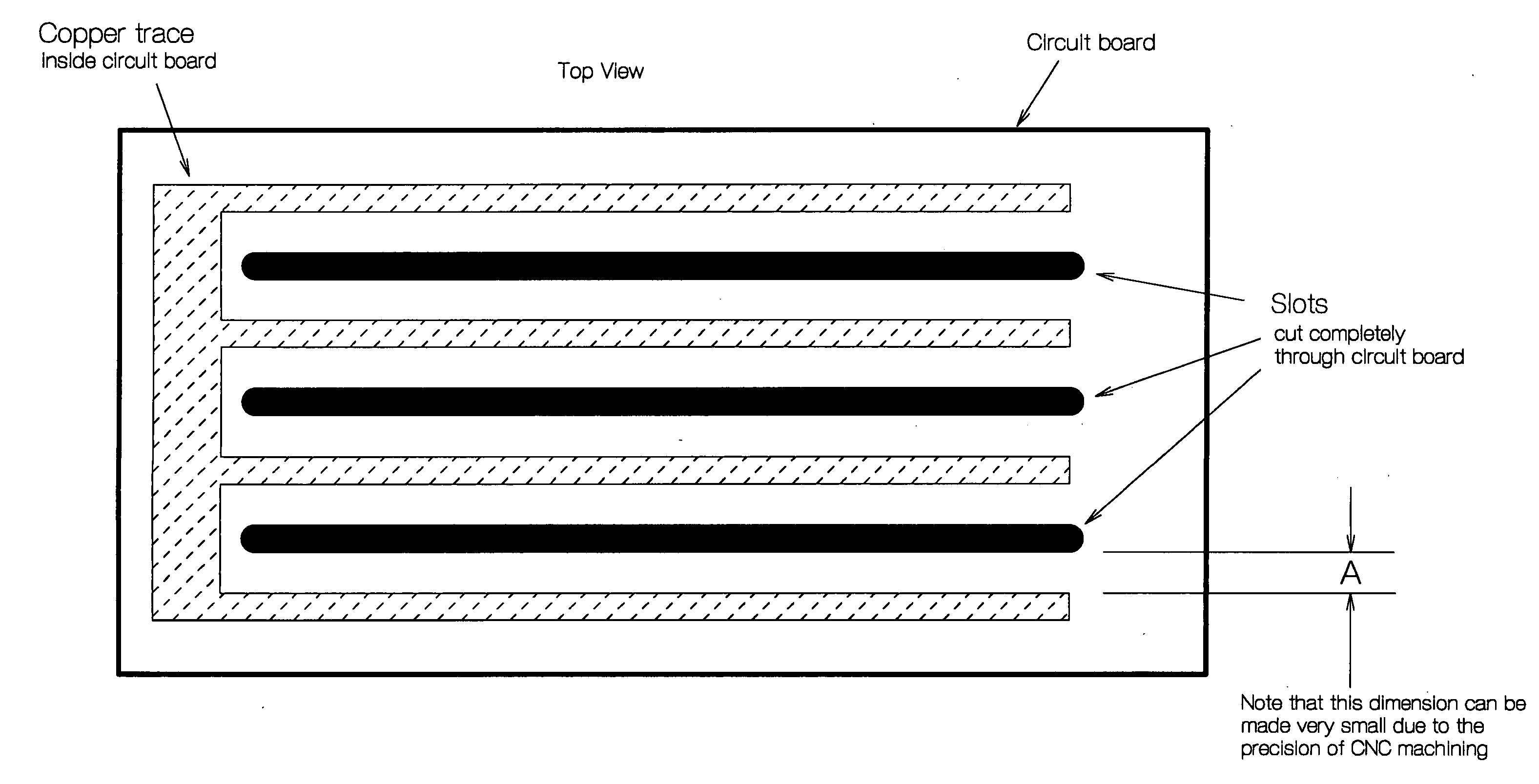
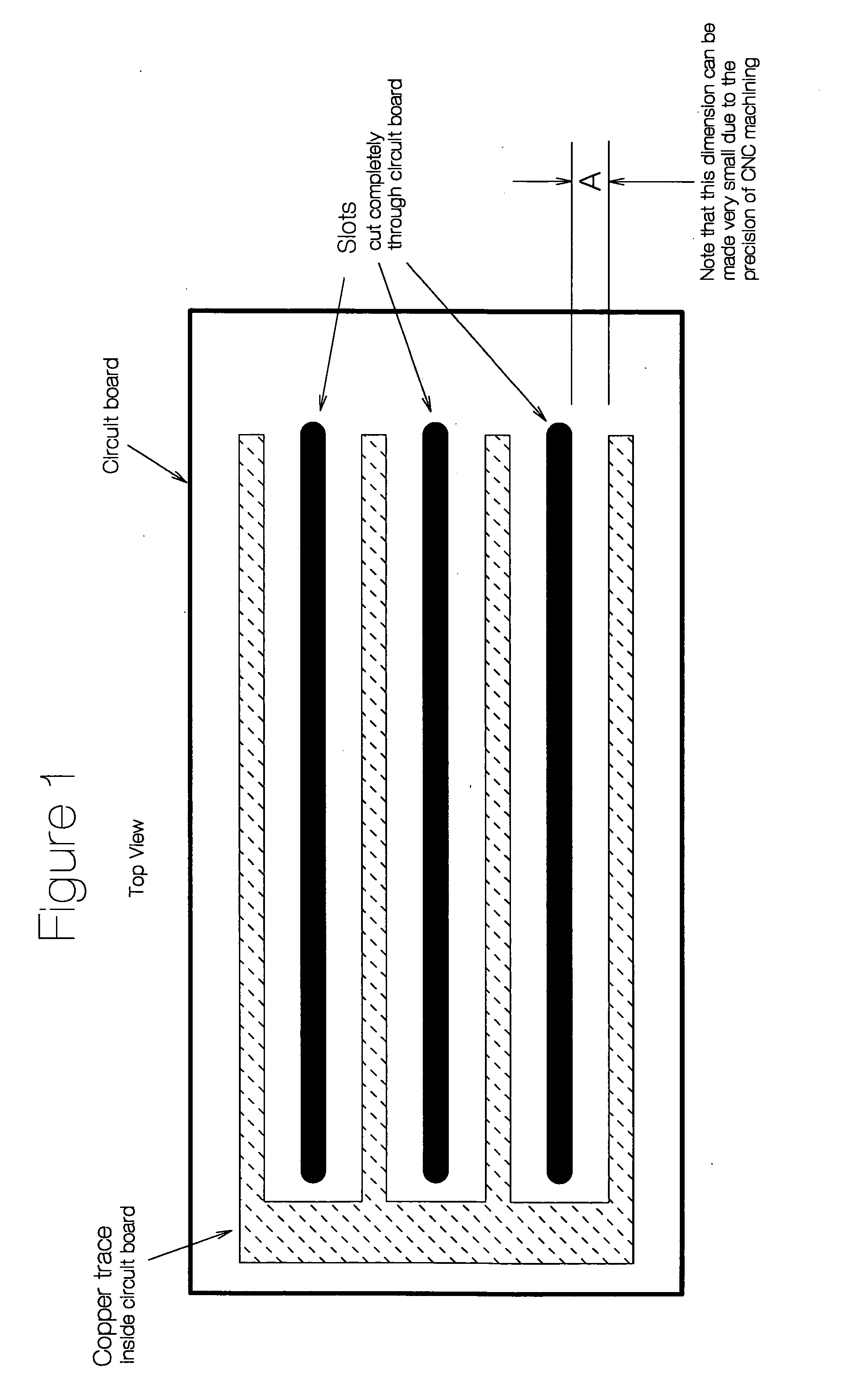
[0023]FIG. 1 shows a representative sample of such a printed circuit board. This shows slots cut completely through the circuit board with the copper traces encapsulated inside the board separated from the edge of the slots so that the copper traces remain completely encapsulated with no exposed copper surfaces anywhere. For clarity, this drawing shows rather large spacing between the slots and the traces (dimension “A”). In practice, the distances would be much smaller with many, closely spaced traces / slots. This is key to producing a high-efficiency speaker and the use of precision methods is essential to this process.

Problems solved by technology

This produces the faultless insulation needed without the use of coatings.
While this lamination process encapsulates the traces perfectly, there remains a very large problem: How does one obtain the needed perforations in the circuit board without damaging or exposing the copper traces inside?

Method used


Image

  • Encapsulated composite electrostatic loudspeaker stator
  • Encapsulated composite electrostatic loudspeaker stator
  • Encapsulated composite electrostatic loudspeaker stator

Examples


Embodiment Construction

[0052] Because circuit board material is inherently an extremely good insulator, a perfectly insulated stator could be made if a way were devised to encapsulate copper traces inside the printed circuit board, where the insulation is perfect. This would provide all the other benefits of a circuit board stator but with flawless, high-value insulation.

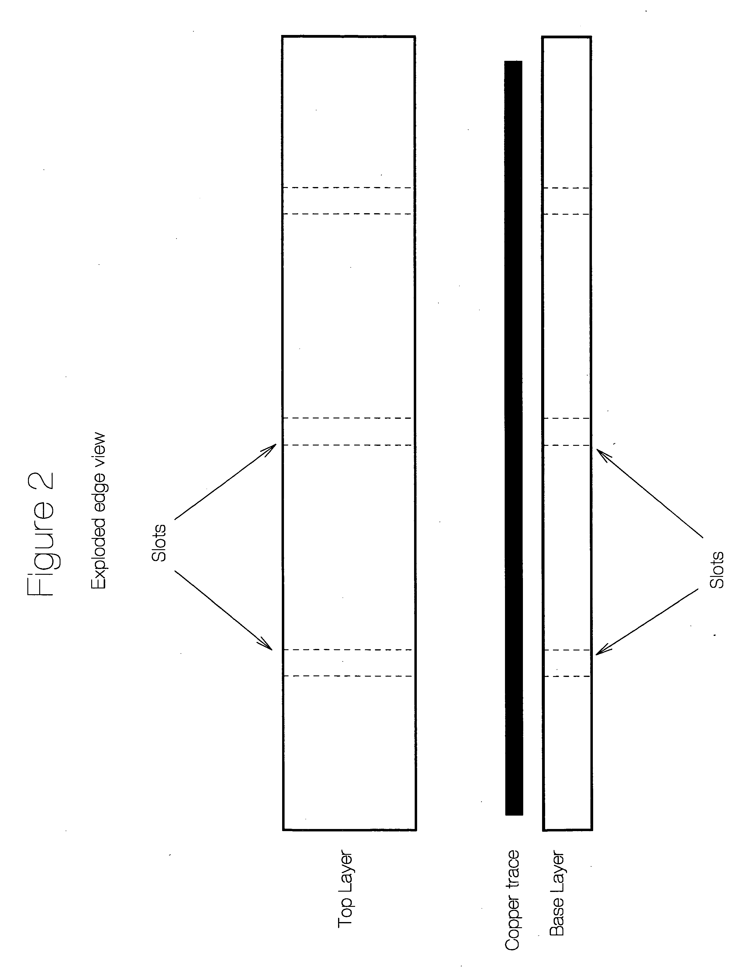
[0053] This invention does exactly that by laminating the copper traces between two circuit boards during their manufacture. This produces the faultless insulation needed without the use of coatings.

[0054] While this lamination process encapsulates the traces perfectly, there remains a very large problem: How does one obtain the needed perforations in the circuit board without damaging or exposing the copper traces inside? The problem is aggravated by the fact that the traces need to be close together for high efficiency.

[0055] The solution to this problem is the use of computer-controlled routing machines. These are now so accurate th...


PUM


Abstract

A method is described whereby composite materials and computer-controlled machining are used to completely encapsulate the conductors in the stators of an electrostatic loudspeaker. This process solves many difficult problems inherent in the construction of such speakers. These include the need for outstanding electrical insulation, avoidance of damage due to arcing, elimination of protective circuitry, durability, a high degree of flatness, high efficiency, light weight, ease of construction, and pleasing appearance.

Description

[0001] An invention is described whereby composite materials are used to completely encapsulate and insulate conductors for use as the stators of an electrostatic loudspeaker. This process solves many difficult problems inherent in the construction of such speakers. These include the need for outstanding electrical insulation, reduced stray capacitance, minimal leakage, avoidance of damage due to arcing, elimination of protective circuitry, strength and durability, a high degree of flatness, high efficiency, light weight, ease of construction, and pleasing appearance. DESCRIPTION: FIELD OF THE INVENTION [0002] The invention pertains generally to electrostatic sound reproducers, and more specifically to an improved type of stator (also known as electrode), which results in outstanding electronic and acoustic performance. Additionally the superior production precision makes construction of a complete electrostatic loudspeaker (ESL) relatively fast and easy with excellent cosmetic resu...

Claims


Application Information

Patent Timeline
IPC IPC(8): H04R19/02H05K1/02
CPCH04R19/02H05K2201/09063H05K1/0256
Inventor BLOODWORTH, CHARLES P.SANDERS, ROGER R.
Owner BLOODWORTH CHARLES P
Learn More