
Projector and drive control of light source lamp for projector

a technology of drive control and light source lamp, which is applied in the direction of projectors, television systems, instruments, etc., can solve the problems of reducing the luminance of illumination light, and no techniques have been proposed to take into account, so as to reduce the potential adverse effects of a variation in luminan

Active Publication Date: 2005-05-05
SEIKO EPSON CORP
View PDF7 Cites 51 Cited by
  • Summary
  • Abstract
  • Description
  • Claims
  • Application Information

AI Technical Summary

Benefits of technology

[0009] The object of the invention is thus to restrain potential adverse effects of a variation in luminance of illumination light emitted by a light source lamp of a projector or a luminance decrease of illumination light emitted by the light source lamp deteriorating with time on the brightness and the contrast ratio of a resulting projected image.

Problems solved by technology

The light source lamp in one projector naturally deteriorates with time and decreases the luminance of illumination light.
No techniques have been proposed to take into account such a difference among the performances of the light source lamps included in multiple projectors of an identical model or a deteriorating performance of the light source lamp in one projector.

Method used


Image

  • Projector and drive control of light source lamp for projector
  • Projector and drive control of light source lamp for projector
  • Projector and drive control of light source lamp for projector

Examples


modified example 1

D1. Modified Example 1

[0076] The procedure of the embodiment compares the measurement results with the preset target values to set the driving power of the light source lamp 52. This is, however, not restrictive at all. The general requirement of the invention is to measure at least one of the brightness and the contrast ratio of a projected image on the screen and set the driving power of the light source lamp according to the measurement result. The setting of the lamp power may thus be determined by a specified operation or by referring to a table representing a variation in setting value against the measurement result.

modified example 2

D2. Modified Example 2

[0077] In the embodiment discussed above, the drive control of the lamp power in the power saving mode sets the driving power of the light source lamp 52 according to both the measured brightness and the measured contrast ratio of the projected image. The driving power of the light source lamp 52 may alternatively be set according to only either one of the measured brightness and the measured contrast ratio of the projected image.

modified example 3

D3. Modified Example 3

[0078] In the embodiment discussed above, the drive control of the lamp power in the power saving mode first regulates the lamp power according to the measured brightness of the projected image and then re-regulates the lamp power according to the measured contrast ratio of the projected image. The order of regulation may be inverted. The regulation of the lamp power first according to the brightness of the projected image and then according to the contrast ratio of the projected image, however, desirably enhances the picture quality of the projected image, compared with the regulation in the reverse order.


PUM


Abstract

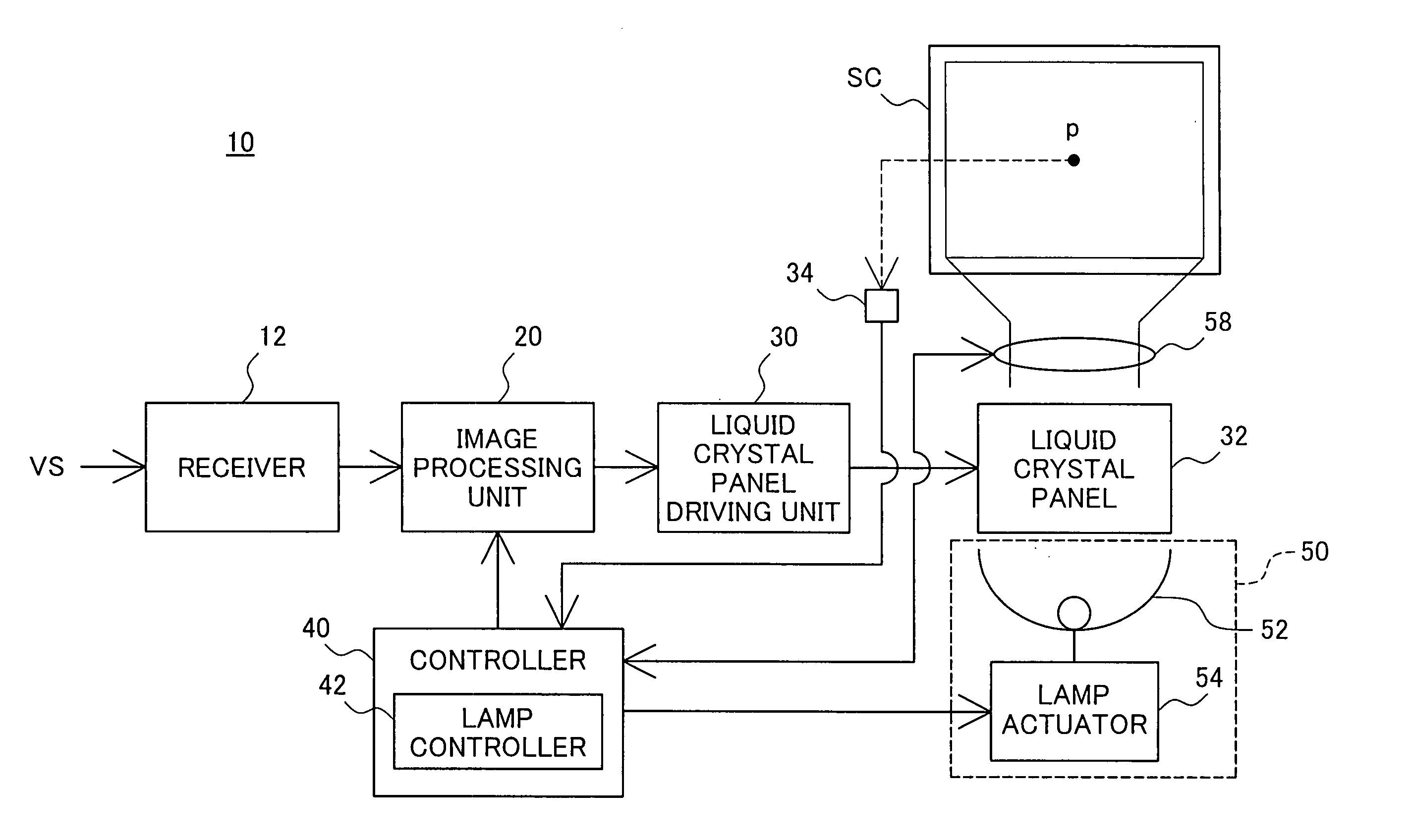
A projector 10 of the invention measures the brightness of an image projected on a screen SC and corrects the measured brightness of the projected image with an input zoom ratio of a projection lens and an input projection distance. The projector 10 compares the corrected brightness of the projected image with a preset target value and sets a driving power of a light source lamp 52 to compensate for a difference between the normalized brightness and the preset target value. This arrangement effectively restrains potential adverse effects of a variation in luminance of illumination light emitted by the light source lamp of the projector on the brightness and the contrast of a resulting projected image.

Description

BACKGROUND OF THE INVENTION [0001] 1. Field of the Invention [0002] The present invention relates to a projector and drive control of a light source lamp included in the projector. [0003] 2. Description of the Related Art [0004] Projectors have been used widely to project an expanded image on a screen. The projectors are used under various conditions on the lightness of working environment, the focal length of a projection lens, and the projection distance. A number of techniques have been proposed to regulate the brightness and the contrast ratio of a projected image according to these parameters for the good viewability of the projected image. [0005] For example, a technique disclosed in Japanese Patent Laid-Open Gazette No. 8-23501 drives a zoom mechanism of a projection lens according to the luminance of a screen and varies the size of a projected image to regulate the brightness and the contrast ratio of the projected image. [0006] A technique disclosed in Japanese Patent Laid-...

Claims


Application Information

Patent Timeline
IPC IPC(8): G02F1/133G02F1/13G02F1/13357G03B21/00G03B21/20G09G3/20G09G3/34G09G3/36H04N5/58H04N5/74H04N9/31H05B37/02H05B41/38
CPCH04N5/58H04N5/74H04N5/7441H04N9/3147H04N21/4318H04N9/3197G03B21/2053H04N21/4122H04N21/42202H04N9/315
Inventor NAKAMURA, KAZUYOSHI
Owner SEIKO EPSON CORP
Learn More